OM-1352-003_w.pdf - 第63页
6-14 Tg1357-ID-SO 0703-003
6-13
Tg1357-ID-SO
Flux type
Select one from "Not Designated" and "Type 1" through "Type 9".
The flux is dispensed from the flux dispensing unit appropriate for the
set flux type, in the flux dispensing units.
Note
When it is set to "Not Designated", the flux is dispensed from the
unit with the smallest slot No. in the mounted flux dispensing units.
Local recog. mark
The individual recognition mark is set.
"Automatic"
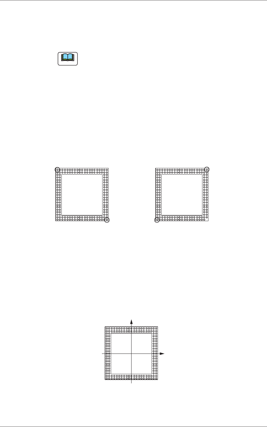
As the ball arrangement for the top component is the same as the land
arrangement on the upper surface of the bottom component, in the case
that the mode is set to "Automatic", the optimum ball is selected in the
ball arrangement in the top component library and the ball position is
used as individual recognition mark position (coordinates).
Top View Top View
Normal
The positions of upper left and
lower right balls are selected as
individual recognition mark coordinates.
In the case that there is no lower right ball:
The optimum positions, such as those of upper
right or lower left balls, are selected automatically.
Fig.31 Automatic
"Manual"
The first and second mark coordinates are entered with the symbol as
shown in the following figure.
Top View
(+)
(+)
Fig.32 Manual
0703-003
6.1 Pattern Program

6-14
Tg1357-ID-SO
0703-003
7-1
Tg1357-ID-SO
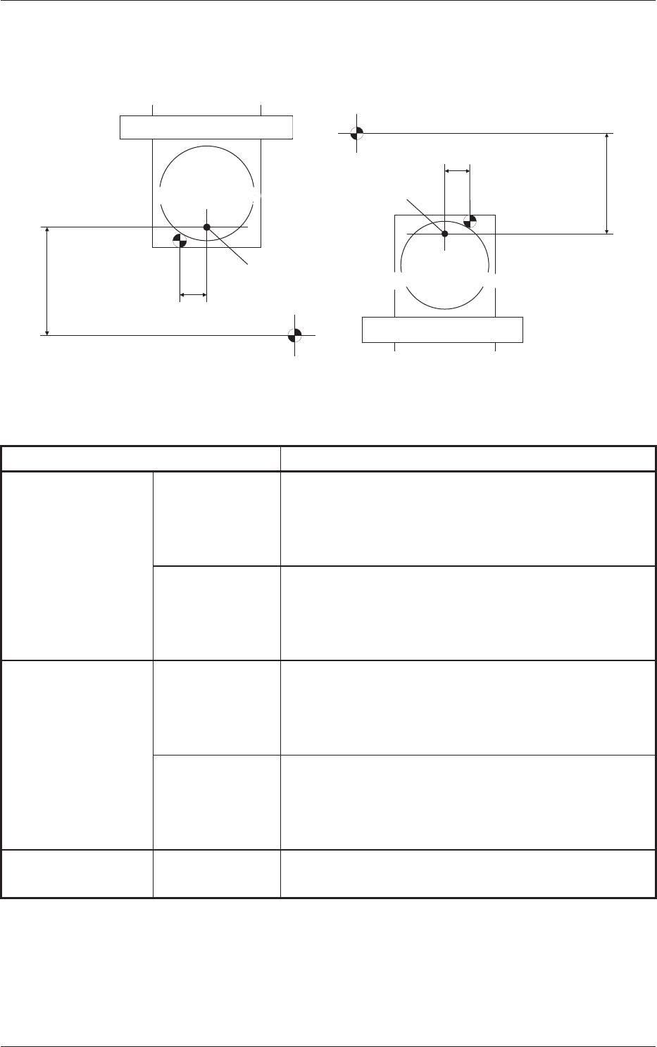
7. Offsets
The following shows the offsets for the flux dispensing unit.
Drum
(Rotational Disk)
Drum
(Rotational Disk)
523.0
21.0
Stage Center Reference
Stage Center Reference
Dispensing Position
Dispensing Position
523.0
21.0
Rear Stage (F1xx, F3xx)
Front Stage (F2xx, F4xx)
Connector 1
Slot Center
X Coordinate
Connector 1
Slot Center
X Coordinate
Drum
(Rotational Disk)
Drum
(Rotational Disk)
Fig. 33
Table 4
Name Details
Dispensing Position X Blocks 1 and 3 Calculated Value X of Slot at Setting Position + 21.0 mm
+ Feeder Offset (A) X
+ Offset X in Flux Transfer Device
+ Component Recognition Correction X
Blocks 2 and 4 Calculated Value X of Slot at Setting Position - 21.0 mm
+ Feeder Offset (A) X
+ Offset X in Flux Transfer Device
+ Component Recognition Correction X
Dispensing Position Y
Blocks 1 and 3 + 523.0 mm
+ Feeder Offset (A) Y
+ Offset Y in Flux Transfer Device
+ Component Recognition Correction Y
Blocks 2 and 4 -523.0 mm
+ Feeder Offset (A) Y
+ Offset Y in Flux Transfer Device
+ Component Recognition Correction Y
Dispensing Position Z Blocks 1, 2, 3,
and 4
Placement Angle
+ Component Recognition Correction Z
0703-003
7. Offsets