OM-1352-003_w.pdf - 第64页
7-1 Tg1357-ID-SO 7. Offsets The following shows the offsets for the flux dispensing unit. Drum (Rotational Disk) Drum (Rotational Disk) 523.0 21.0 Stage Center Reference Stage Center Reference Dispensing Position Dispensi…

6-14
Tg1357-ID-SO
0703-003
7-1
Tg1357-ID-SO
7. Offsets
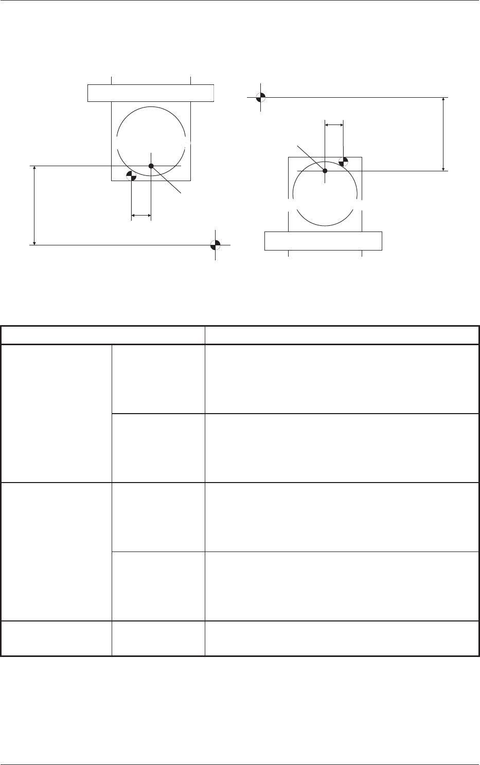
The following shows the offsets for the flux dispensing unit.
Drum
(Rotational Disk)
Drum
(Rotational Disk)
523.0
21.0
Stage Center Reference
Stage Center Reference
Dispensing Position
Dispensing Position
523.0
21.0
Rear Stage (F1xx, F3xx)
Front Stage (F2xx, F4xx)
Connector 1
Slot Center
X Coordinate
Connector 1
Slot Center
X Coordinate
Drum
(Rotational Disk)
Drum
(Rotational Disk)
Fig. 33
Table 4
Name Details
Dispensing Position X Blocks 1 and 3 Calculated Value X of Slot at Setting Position + 21.0 mm
+ Feeder Offset (A) X
+ Offset X in Flux Transfer Device
+ Component Recognition Correction X
Blocks 2 and 4 Calculated Value X of Slot at Setting Position - 21.0 mm
+ Feeder Offset (A) X
+ Offset X in Flux Transfer Device
+ Component Recognition Correction X
Dispensing Position Y
Blocks 1 and 3 + 523.0 mm
+ Feeder Offset (A) Y
+ Offset Y in Flux Transfer Device
+ Component Recognition Correction Y
Blocks 2 and 4 -523.0 mm
+ Feeder Offset (A) Y
+ Offset Y in Flux Transfer Device
+ Component Recognition Correction Y
Dispensing Position Z Blocks 1, 2, 3,
and 4
Placement Angle
+ Component Recognition Correction Z
0703-003
7. Offsets
7-2
Tg1357-ID-SO
0703-003
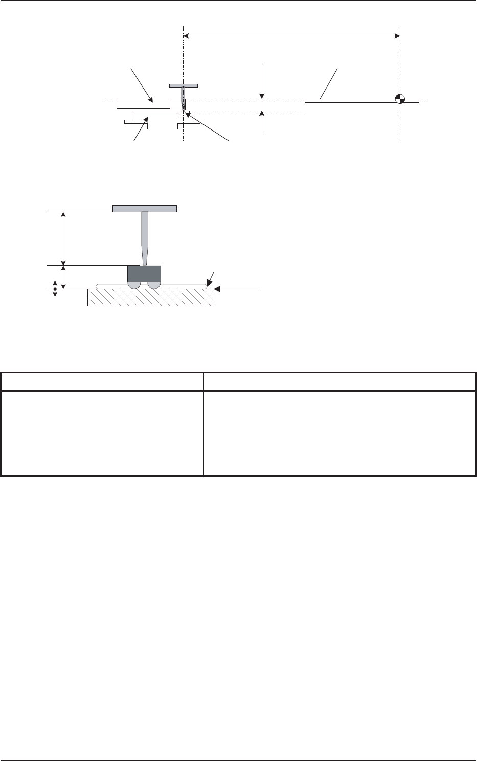
9.5
523.0
PCB Positioning
Upper Surface
Dispensing Reference
Surface
Squeegee
Drum (Ratational Disk)
Flux Dispensing Unit
Stage Center
Reference
Dispensing Reference Surface
Flux (Coating Pressure: 10 to 100
�m)
Dispensing Level
Component
Thickness (t)
Nozzle Length
At the time of component dipping
Dispensing Position
Fig.34
Table 5
Name Details
Height from Upper Surface of PCB 9.5 mm
+ Feeder Offset (A) L
+ Offset L in Flux Dispensing Unit
- Component Thickness
+ Dispensing Level
7. Offsets