OM-1352-003_w.pdf - 第74页
10-1 Tg1357-ID-SO 0703-003 (M806WFX--0102) 10. Material 10. Material 10.1 Electrical Circuit Diagrams Flux Dispensing Unit Circuit Diagram Drawer Connector for Feeder GXH Main Body Side Connection Confirmation Signal [OU…

9-2
Tg1357-ID-SO
0703-003
10-1
Tg1357-ID-SO
0703-003 (M806WFX--0102)
10. Material
10. Material
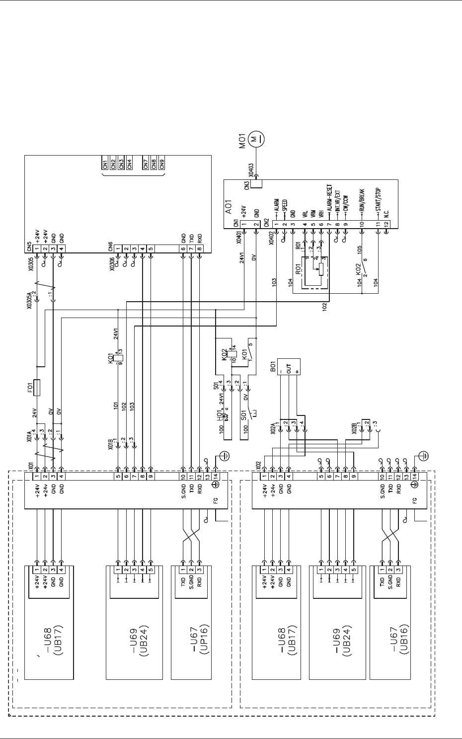
10.1 Electrical Circuit Diagrams
Flux Dispensing Unit Circuit Diagram
Drawer Connector for Feeder
GXH Main Body Side
Connection Confirmation Signal [OUT]
Not Used
(Feeder Base)
Feeder Power
Distribution
Feeder Base I/O
Feeder Base Serial
Communications
Feeder Power
Distribution
Feeder Base I/O
Feeder Base Serial
Communications
(Feeder Base)
Drawer Connector for Feeder
Rotation Start
Alarm Reset
Driver Alarm
Communications
Ready
Feeder Connec-
tion Check
Not Used
Not Used
Rotation Detection
Remainder Detection
Feeder Connec-
tion Check
Rotation Detection Sensor
Flux Transfer Device
Servoamplifier
Lane 1 Feed Command [IN]
Lane 2 Feed Command [IN]
Ready Signal [OUT]
Connected Check Signal
(For Communications Confirmation) [OUT]
10-2
Tg1357-ID-SO
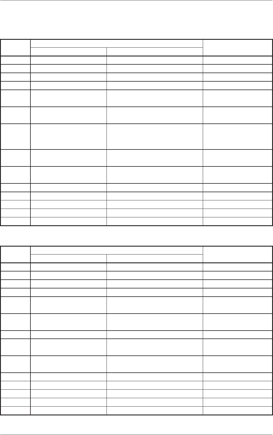
10.2 I/O Check Table of Drawer Connector Pins
10.2 I/O Check Table of Drawer Connector Pins
Drawer Connector 1 (Low Address Side) Table 11
Pin No.
Flux Dispensing Unit
Ref.: Tape Feeders
Signal Name Description
1 +24V 24 V DC Power Supply
←
2 +24V 24 V DC Power Supply
←
3 GND GND of 24 V DC Power Supply
←
4 GND GND of 24 V DC Power Supply
←
5 IN: Rotation Start/Stop ON (L): Rotation OFF (H): Stop
(Connection with DC Motor Driver)
IN: Lane 1 Feeding
Command
6 IN: Alarm Reset ON (L): Set
(Connection with DC Motor Driver)
IN: Lane 2 Feeding
Command
7 OUT: DC Motor Drive
Alarm
ON (L): Normal
OFF (H): Abnormal
(Connection with DC Motor Driver)
OUT: Feeding Ready
8 OUT: Communications
Ready
RS232C Communications Available
←
9 OUT: Connection Check:
GND Return
Check of Connection with Feeder
Base Slot
←
10 GND (RS232C) Signal GND
←
11
TXD (RS232C) Transmission Line
←
12 RXD (RS232C) Reception Line
←
13 NC Not Used
←
14 FG (Frame Ground) Case Grounding
←
Drawer Connector 2 (High Address Side) Table 12
Pin No.
Flux Dispensing Unit
Ref.: Tape Feeders
Signal Name Description
1 +24V 24 V DC Power Supply
←
2 +24V 24 V DC Power Supply
←
3 GND GND of 24 V DC Power Supply
←
4 GND GND of 24 V DC Power Supply
←
5 IN: Reserved Reserved IN: Lane 1 Feeding
Command
6 IN: Reserved Reserved IN: Lane 2 Feeding
Command
7 OUT: Rotation Detection Duty Ratio 1:1 of ON (L)/OFF (H) OUT: Feeding Ready
8 OUT: Reserved Reserved OUT: Communications
Ready
9 OUT: Connection Check:
GND Return
Check of Connection with Feeder
Base Slot
←
10 GND (RS232C) Signal GND
←
11
TXD (RS232C) Transmission Line
←
12 RXD (RS232C) Reception Line
←
13 NC Not Used
←
14 FG (Frame Ground) Case Grounding
←
0703-003