ECM-B3M-C20807SS1伺服电机-资料.pdf - 第30页
27 ECM - B3 M - C A 06 04 R S 1 Commutation Motor H L E …
26
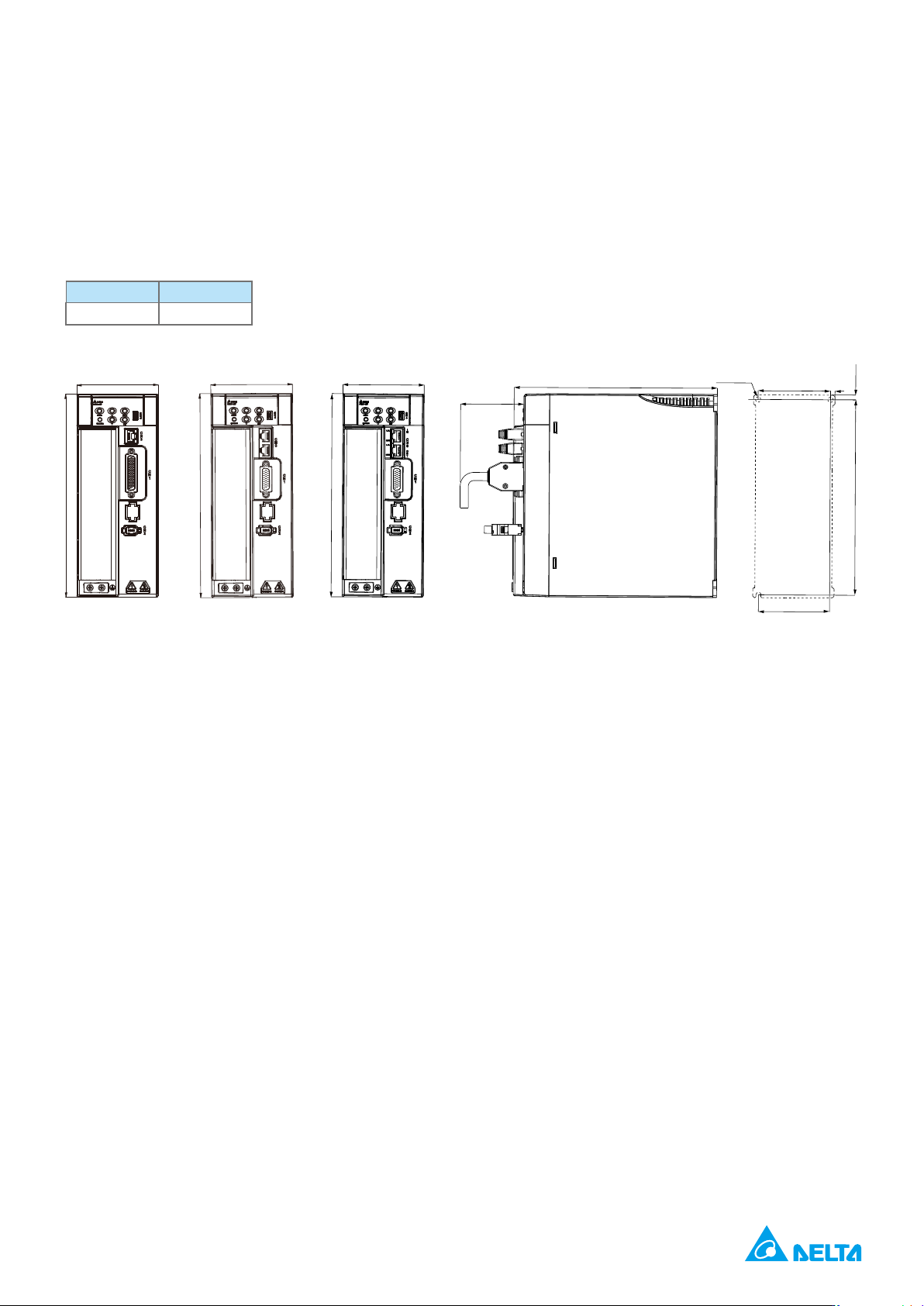
4.5 kW / 5.5 kW / 7.5 kW
mm (inch)
90(3.5)
225(8.9)
70(2.8)
225(8.9)
78.8(3.1)
216.4(8.52)
80.2(3.16)
5(0.19)
Ø5.7(0.22)-3X
5.4(0.21)
90(3.5)
225(8.9)
90(3.5)
225(8.9)
B3-L
B3-M/F
B3-E
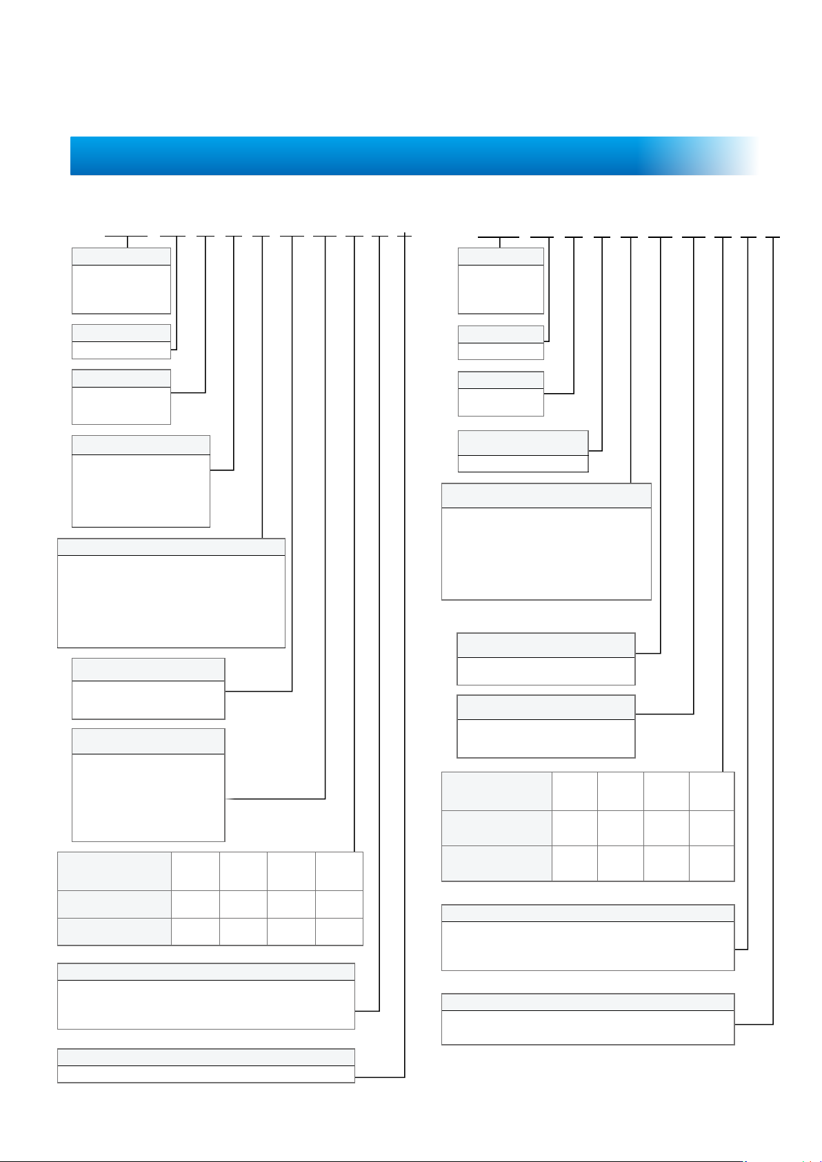
27
ECM
-
B3 M - C A 06 04 R S 1
Commutation
Motor
H
L
E
Encoder Type
A
:
2 :
w/o Oil
Seal
w/o Oil
Seal
with Oil
Seal
with Oil
Seal
C* D*
S
7
Special Code
ECM
-
A3 H - C Y 06 04 R S 1
Product Name
:
Electronic
H
L
Rated Voltage and Speed
C
Encoder Type
*1
:
*2
*1
*2
w/o Oil
Seal
w/o Oil
Seal
with Oil
Seal
with Oil
Seal
C D
S
*Not standing models
*Shafts of special diameter are used for 400 W motors with the frame size of 80 mm
Special Code
Servo Motor Model Information
04:40 mm 06:60 mm
08:80 mm 10
:100 mm
:
18
:180 mm
01
:100 W 02
:200 W
04
:400 W 07:750 W
08
:850 W 10
:
:
:
18
::
:
:
55
:
:
04:40mm 06:60mm
08:80mm
:50W 01:100W
02:200W 04:400W
07:750W
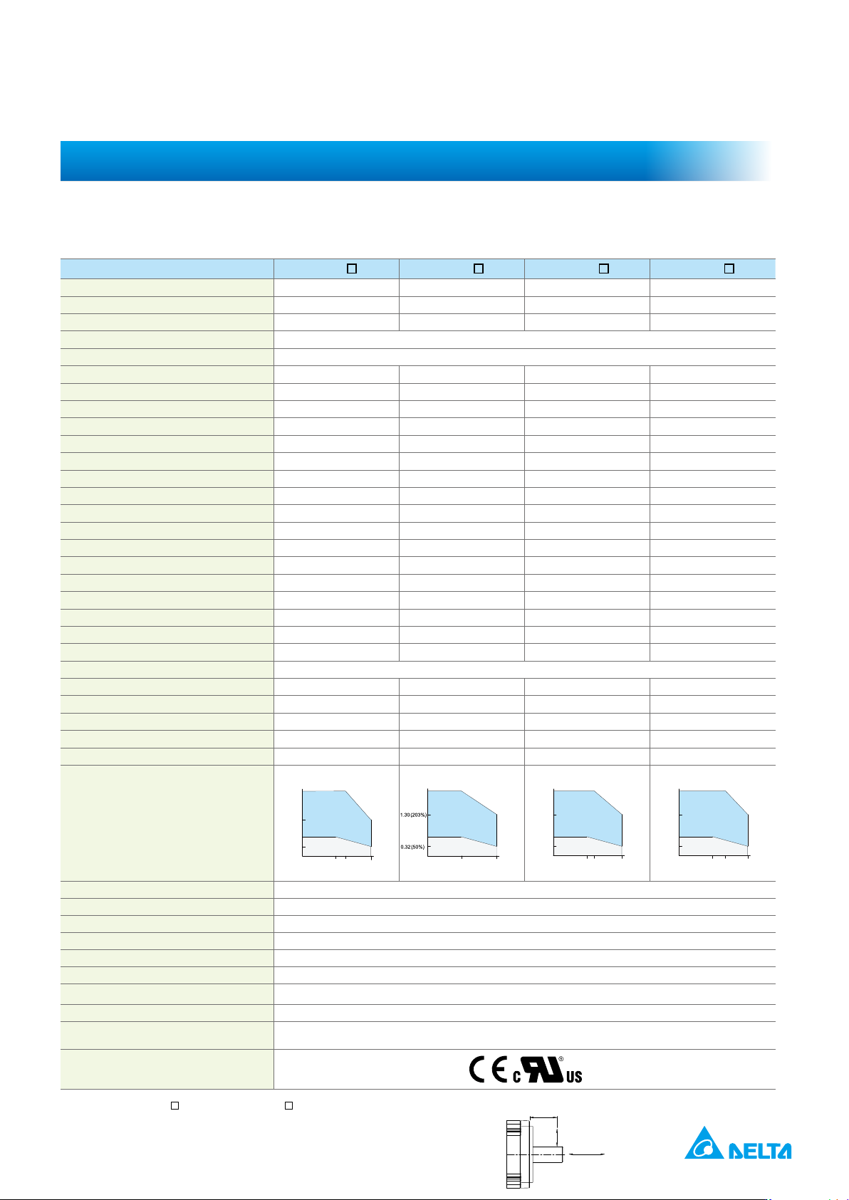
28
2
0401
*1
2
0602
*1
2
0604
*1
2
*1
*2
6000
1.42 2.40
6.62 9.47 9.42
with brake
kg.m
2
0.0299 0.141
kg.m
2
with brake
0.91
with brake
16.96 19.76
4.71 2.04
19.1
Weight –
with brake
*5
78 245 245
*5
54 74 74 147
24 V
DC
±
8
20 20 20 20
50 50 60
10 10 5 5
Torque (N - m)
Speed (rpm)
3000 6000
3300
0.16 (50%)
0.32 (100%)
1.12 (350%)
0.52(162%)
Intermittent Duty Zone
Continuous Duty Zone
3000 6000
0.64 (100%)
2.24 (350%)
Torque (N - m)
Speed (rpm)
Intermittent Duty Zone
Continuous Duty Zone
3000 60003300
0.64 (50%)
1.27 (100%)
4.45 (350%)
2.81(221%)
Torque (N - m)
Speed (rpm)
Intermittent Duty Zone
Continuous Duty Zone
3000 6000
3700
0.63 (50%)
1.27 (100%)
4.45 (350%)
3 (236%)
Torque (N - m)
Speed (rpm)
Intermittent Duty Zone
Continuous Duty Zone
Insulation Class
Insulation Strength
Operating Temperature
4
Storage Temperature
4
1. In the servo motor model name,
1
represents the motor inertia and
2
represents the encoder type.
2. The rated torque is the continuous permissible torque between 0 to 40ºC operating temperature which is suitable
for the servo motor mounted with the following heat sink dimensions.
F40, F60, F80: 250 mm x 250 mm x 6 mm
Material: aluminum
3. The built-in servo motor brake is only for keeping the object in a stopped state.
Do not use it for deceleration or as a dynamic brake
4. If the operating temperature is over 40ºC, refer to the power derating curves of B3 motors on page 37.
Electrical Specications
Radial load
Thrust / axial load
LR-5