OM-1606-006w_GT-28x.pdf - 第111页
OM-1606 6. Splicing 6-9 0908-001 6.5.2 Cutting T ape on Feeder Side (1) Prepare the tape on the feeder side. (2) Cut the tape on the feeder side. Set the tape on the pilot pins and cut it. • T ake care not to cut any com…
OM-1606
6-8
6. Splicing
0908-001
6.5 8 mm Width Tape Splicing Procedure
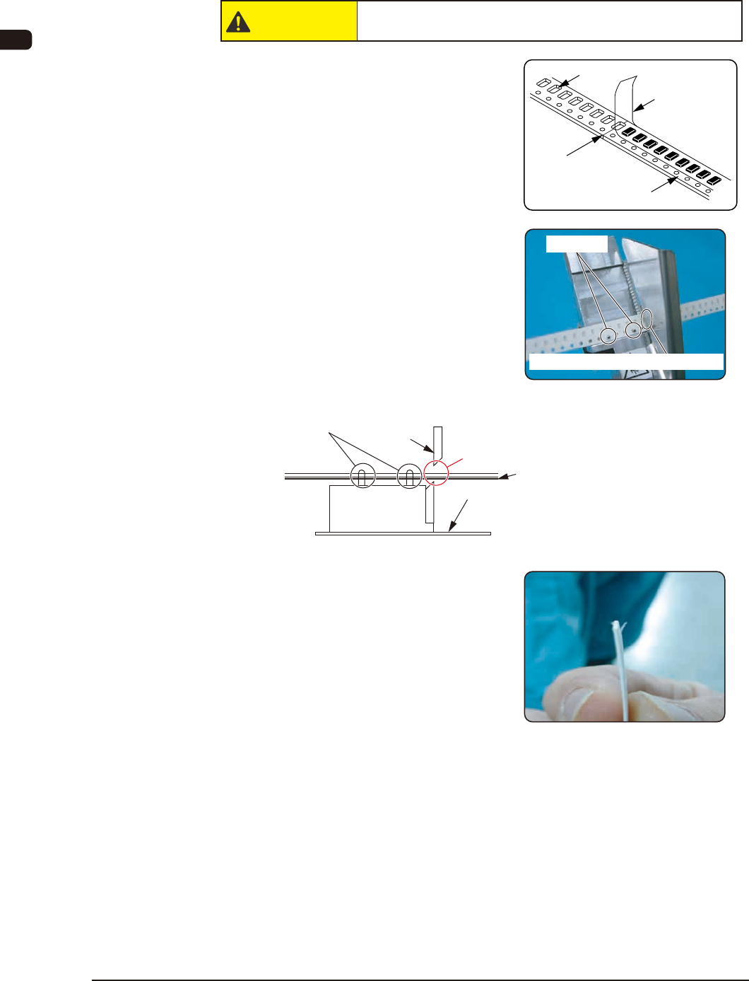
6.5.1 Cutting New Tape
CAUTION
Cut it off with the greatest care so as not to cut your nger.
(1) Prepare a new tape.
Peel off the cover tape up to the
splicing position.
(2) Cut the tape, using the tape cutting
jig.
Attach the tapes onto the tape cut
jig and cut the tapes with cover tape
and carrier tape overlapped.
•
Take care not to cut any component
in order to prevent damage to the
tape cutting jig.
There should be no component here.
Mirror Surface
(Make sure that there is no component in
the component compartment hole on the
rear side of the carrier tape).
Pilot Pins
Scissors
Cover Tape
(3) The preparation of new tape has
been completed.
Make sure that the end of the cover
tape is peeled off a little from the
carrier tape.
Cover Tape
Carrier Tape
Splicing Position
(Cut Position)
Component Compartment
Hole
Pilot Pins
Cut the tape at the Component Compartment Hole.
OM-1606
6. Splicing
6-90908-001
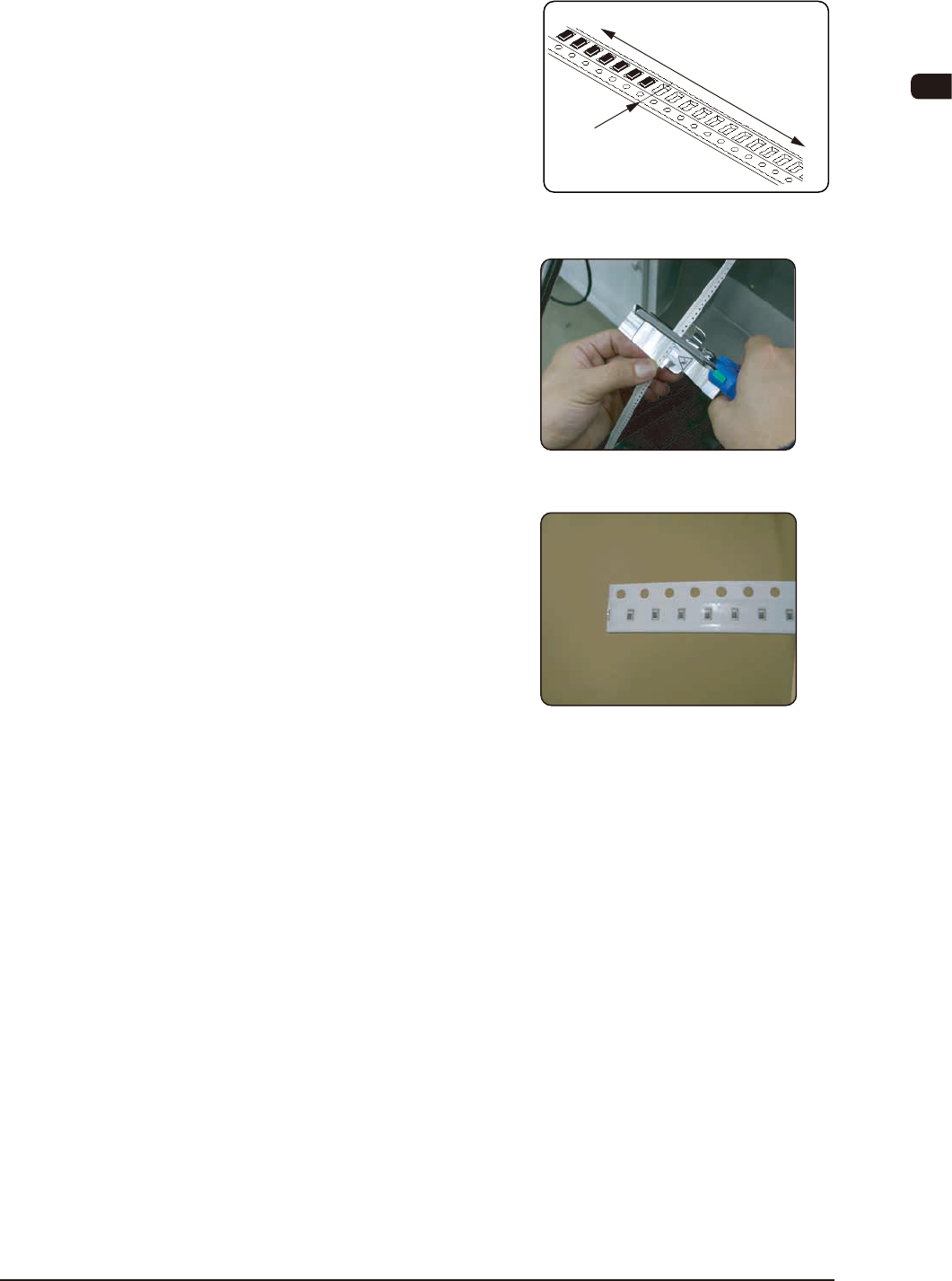
6.5.2 Cutting Tape on Feeder Side
(1) Prepare the tape on the feeder side.
(2) Cut the tape on the feeder side.
Set the tape on the pilot pins and cut
it.
•
Take care not to cut any component
in order to prevent damage to the
tape cutting jig.
(3) The preparation of the tape on the
feeder side has been completed.
If it tends to bend, correct it.
Feeder Side
Section where the
components are
not included
Section where
the components are included
Cut Position
OM-1606
6-10
6. Splicing
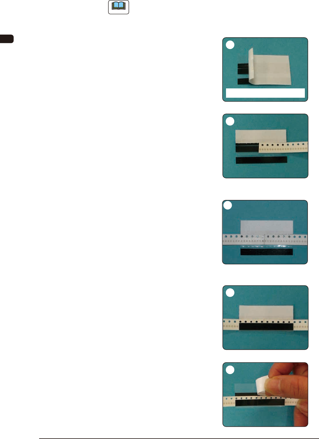
6.5.3 Tape Splicing Procedure (For 8 mm : HT8RE)
Note
When part of black tape is left on the peeling paper, return the peeling
paper and press the tape against the paper. Then, peel off the peeling paper
again.
Peel off the white peeling paper
located on the section with oblique
lines in the above gure.
As there is a margin for peeling, peel
it from that section.
First, adhere the cover tape surface
of the new tape onto the splicing
tape.
Align the tape border of the sprocket
hole side with the left white peeling
paper, and so adhere it that the joint
position is located at the center.
Adhere the cover tape surface on the
feeder side.
Align the tape border of the sprocket
hole side with the left white peeling
paper, and so adhere it that there is
no gap on the joint position with the
new tape.
Bend the splicing tape along the
perforations and adhere it onto the
carrier tape.
Peel off the white peeling paper from
the sprocket hole border side.
1005-002
2
5
4
1
Other Side of Splicing Tape
3