OM-1606-006w_GT-28x.pdf - 第122页
OM-1606 6-20 6. Splicing 0908-001 6.7 24 mm Width T ape Splicing Procedure 6.7.1 Cutting New T ape CAUTION Cut it off with the greatest care so as not to cut your nger . (1) Prepare a new tape. Peel off the cover tape u…
OM-1606
6. Splicing
6-190908-001
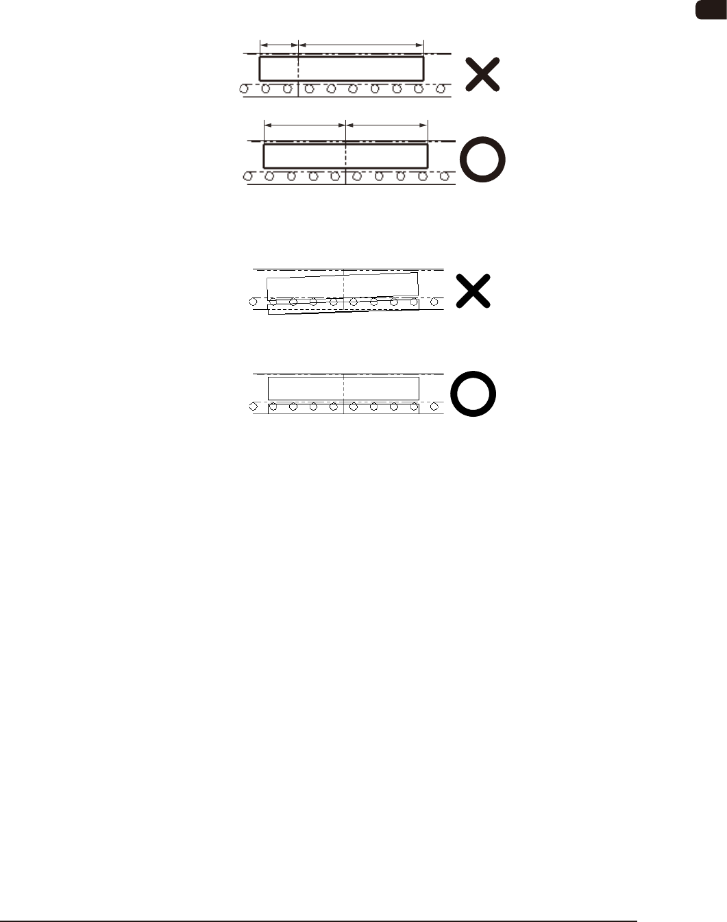
(3) When the splicing tape is adhered, set the center of the cut position of
the splicing tape.
If the tape is deviated along the direction of the splicing tape, the tape
joint section might come off.
Positional Deviation
(4) Do not let the splicing tape swell very far out from the carrier tape.
If there is any swell out, a feed error might occur.
OM-1606
6-20
6. Splicing
0908-001
6.7 24 mm Width Tape Splicing Procedure
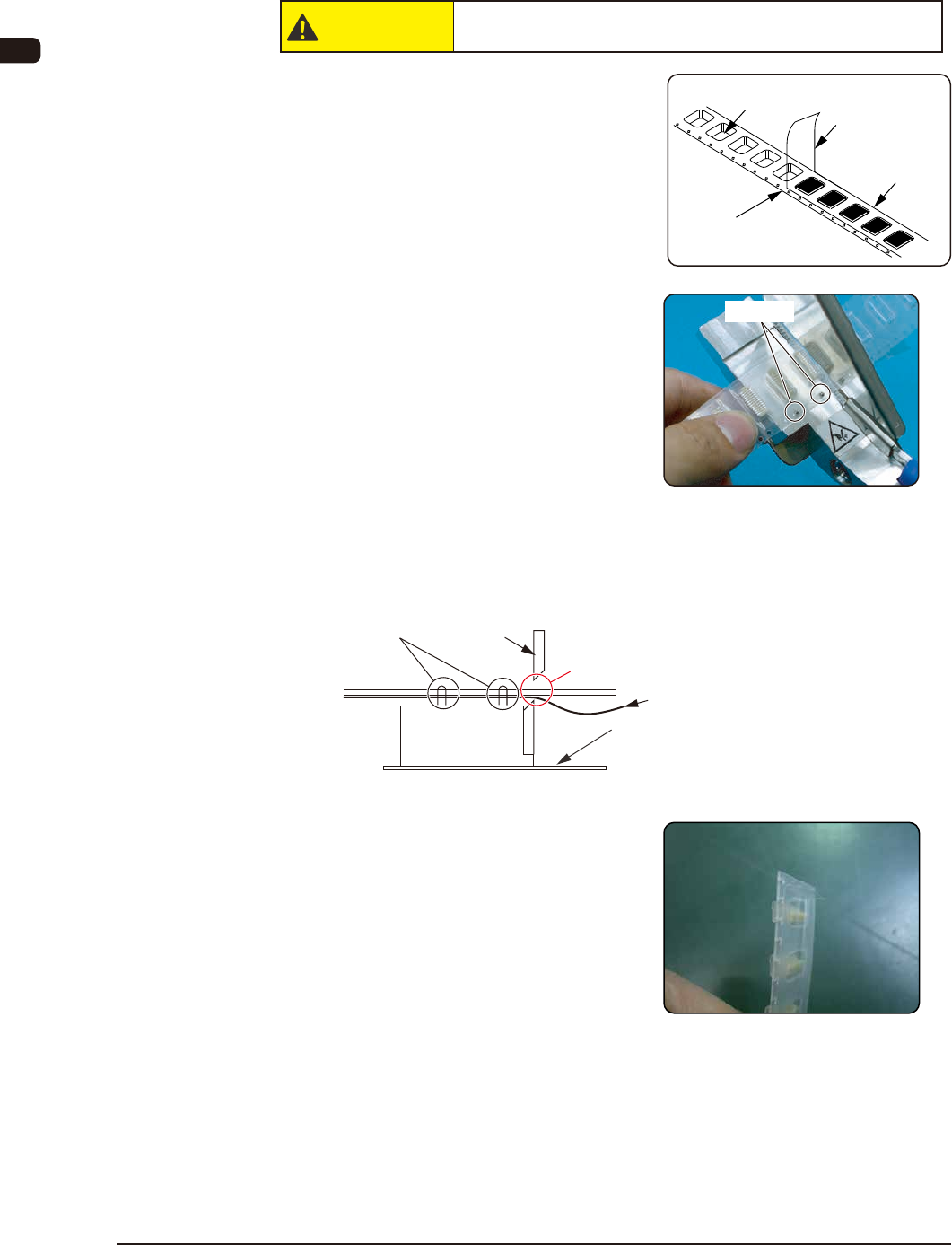
6.7.1 Cutting New Tape
CAUTION
Cut it off with the greatest care so as not to cut your nger.
(1) Prepare a new tape.
Peel off the cover tape up to the
splicing position.
(2) Cut the tape, using the tape cutting
jig.
Set the new tape on the pilot pins so
that the cover tape is turned down.
Then, cut the carrier tape together
with the cover tape.
•
Take care not to cut any component
in order to prevent damage to the
tape cutting jig.
•
In the case of 12 mm or 20 mm pitch,
the pilot pins are not used.
There should be no component here.
Mirror Surface
(Make sure that there is no component in
the component compartment hole on the
rear side of the carrier tape).
Pilot Pins
Scissors
Cover Tape
(3) The preparation of new tape has
been completed.
Pilot pins
Cover Tape
Splicing Position
(Cut Position)
Carrier Tape
Component Compartment
Hole
OM-1606
6. Splicing
6-210908-001
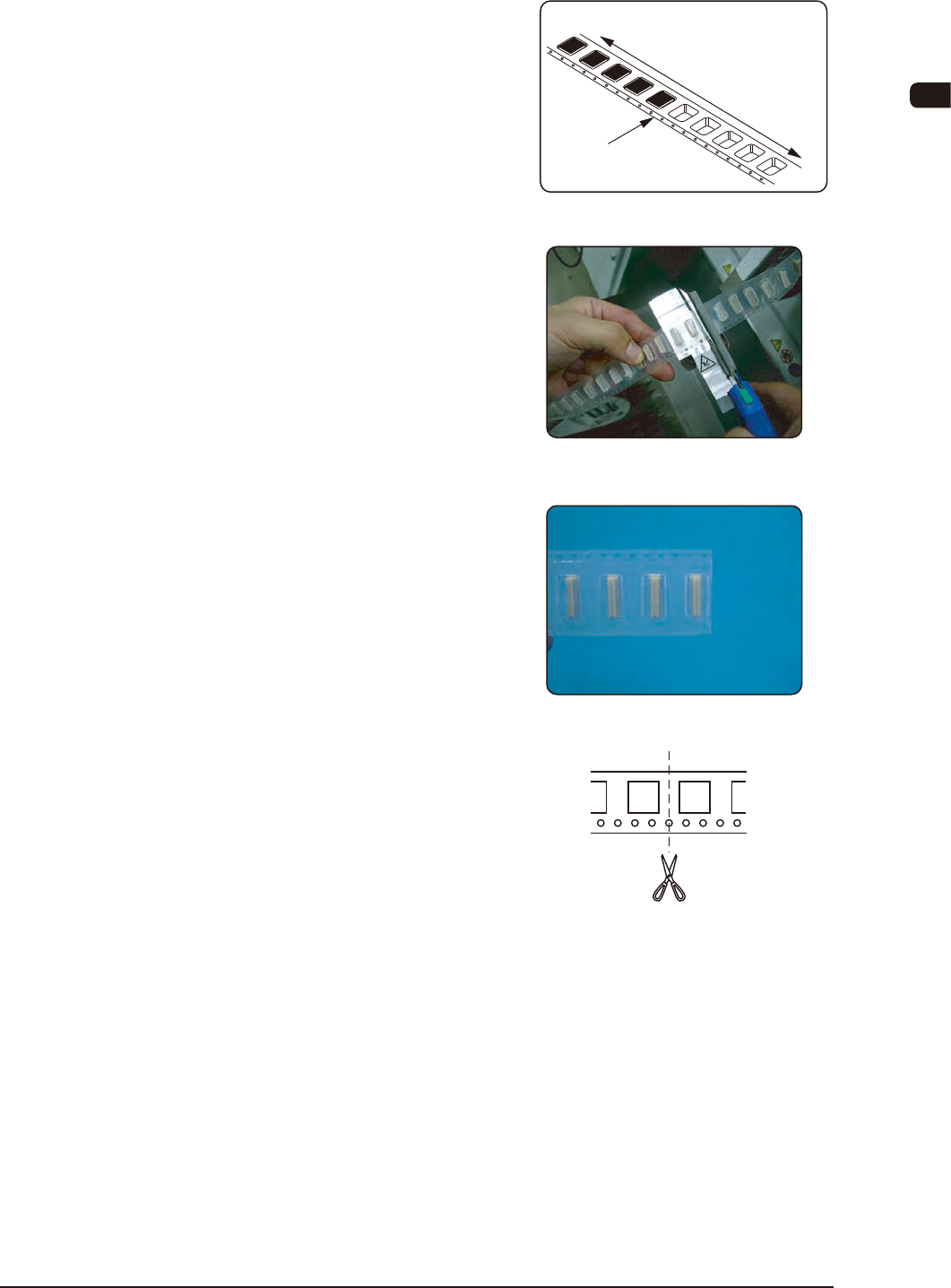
6.7.2 Cutting Tape on Feeder Side
(1) Prepare the tape on the feeder side.
(2) Cut the tape on the feeder side.
Set the tape on the pilot pins and cut
it.
•
Take care not to cut any component
in order to prevent damage to the
tape cutting jig.
•
In the case of 12 mm or 20 mm pitch,
the pilot pins are not used.
(3) The preparation of the tape on the
feeder side has been completed.
If it tends to bend, correct it.
•
In the case of 12 mm or 20 mm pitch,
do not use the pilot pins. Cut the tape
at the center position between the
two carrier pockets.
Cut the tape so that the carrier tapes
are not overlapped each other at the
joint section.
Feeder Side
Section where the
components are
not included
Section where the components
are included
Cut Position
Cut Position