OM-1606-006w_GT-28x.pdf - 第136页
OM-1606 6-34 6. Splicing 0908-001 6.9.2 Cutting T ape on Feeder Side (1) Prepare the tape on the feeder side. (2) Cut the tape on the feeder side. Set the tape on the pilot pins and cut it. • The tape cut jig can deal wi…

OM-1606
6. Splicing
6-331005-001
(3) The preparation of new tape has
been completed.
OM-1606
6-34
6. Splicing
0908-001
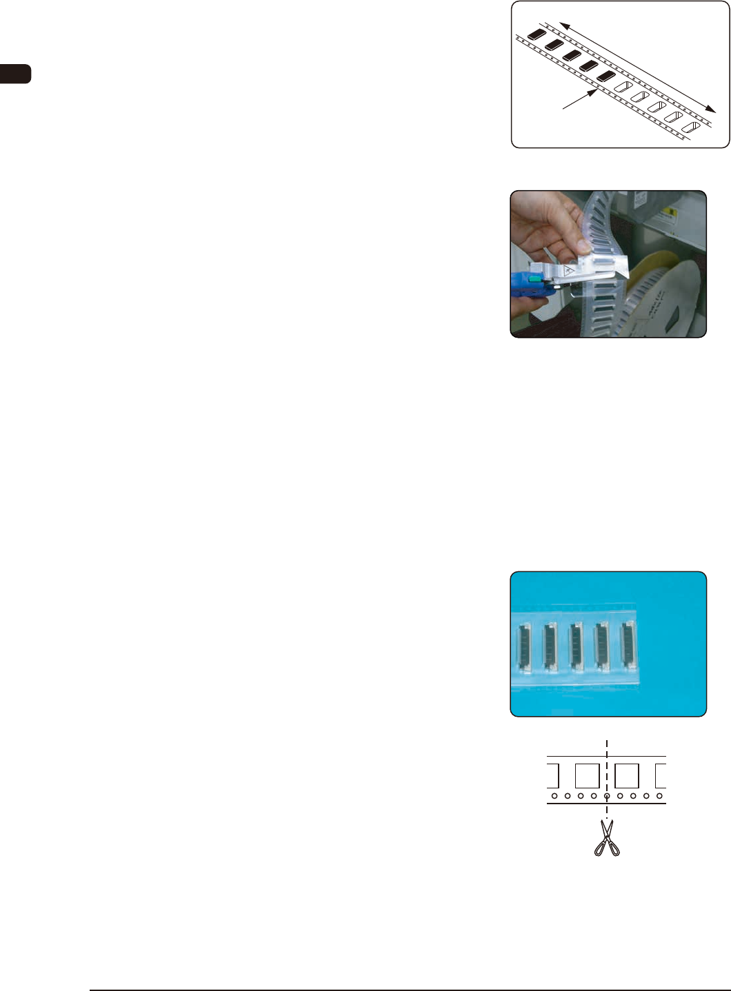
6.9.2 Cutting Tape on Feeder Side
(1) Prepare the tape on the feeder side.
(2) Cut the tape on the feeder side.
Set the tape on the pilot pins and cut
it.
•
The tape cut jig can deal with tape
with up to 32 mm in width. Cut it
twice.
Otherwise, use scissors if available
and cut it so that the cut position is
not deviated.
•
Take care not to cut any component
in order to prevent damage to the
tape cutting jig.
•
In the case of 12 mm, 20 mm, 28 mm
or 36 mm pitch, the pilot pins are not
used.
(3) The preparation of the tape on the
feeder side has been completed.
If it tends to bend, correct it.
•
In the case of 12 mm, 20 mm, 28
mm or 36 mm pitch, do not use the
pilot pins. Cut the tape at the center
position between the two carrier
pockets.
Cut the tape so that the carrier tapes
are not overlapped each other at the
joint section.
Feeder Side
Section where the
components are
not included
Section where the
components are included
Cut Position
Cut Position
OM-1606
6. Splicing
6-35
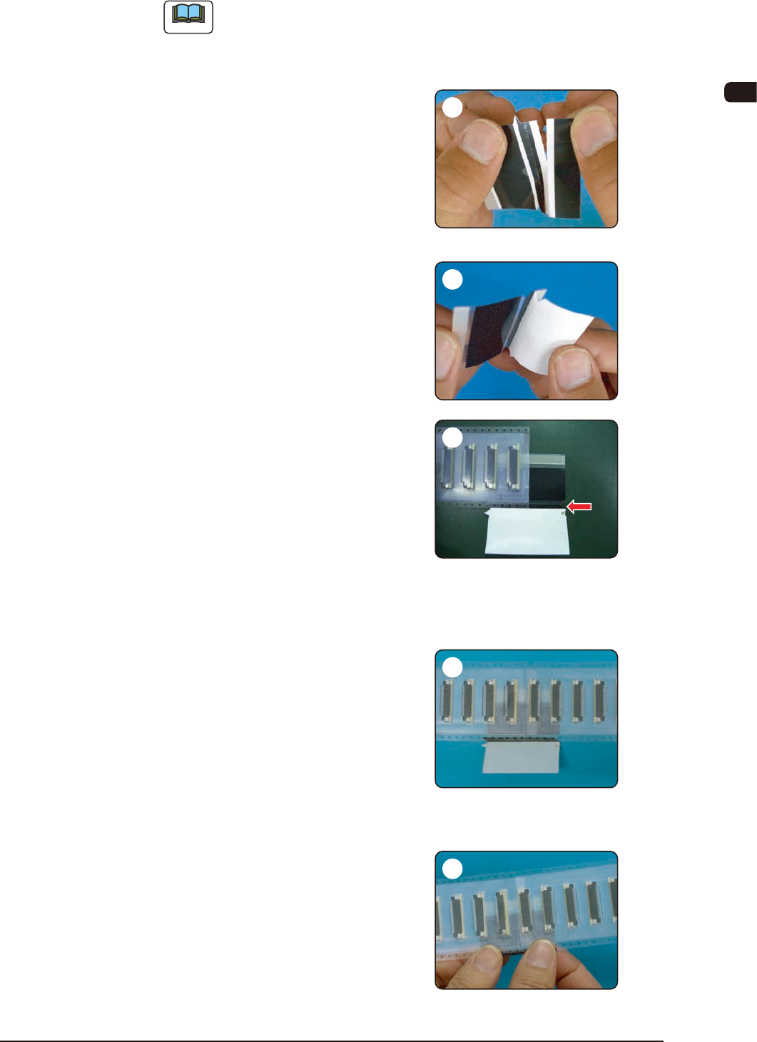
6.9.3 Tape Splicing Procedure (For 24 mm or more : FC24QE)
Note
When part of black tape is left on the peeling paper, return the peeling
paper and press the tape against the paper. Then, peel off the peeling paper
again.
Cut off the splicing tape along the
perforations.
Peel off the white peeling paper
on the splicing tape up to the
perforations and bend it.
First, adhere the cover tape surface
of the new tape onto the splicing
tape.
Align the folded perforations with the
tape border of the reference sprocket
hole side and so adhere it that the
joint position is located at the center.
Adhere the cover tape surface on the
feeder.
Align the folded perforations with the
tape border of the reference sprocket
hole side and so adhere it that there
should be no gap on the joint position
with the new tape.
Peel off the peeling paper, fold the
splicing tape along the perforations
and adhere it to the carrier tape on
the reference sprocket hole border
side.
In order to adhere the splicing tape
securely, press and rub the surface
of the transparent lm entirely.
0908-001
1
2
3
4
5