OM-1606-006w_GT-28x.pdf - 第139页
OM-1606 6. Splicing 6-37 0908-001 Peel off the transparent lm. Peel off the white peeling paper on the splicing tape which has been cut in Step 1 and 7 . Adhere two tapes to the rear side (embossed bottom surface) of th…
OM-1606
6-36
6. Splicing
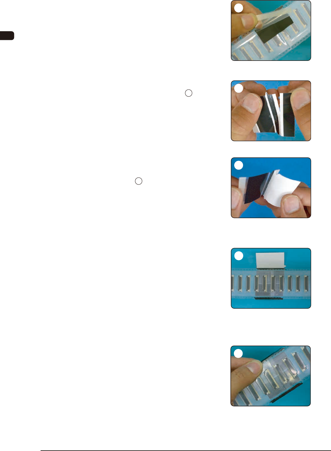
Peel off the transparent lm.
Cut off the other splicing tape the
same as shown in Step 1 .
Peel off the white peeling paper up to
the perforations and fold it as shown
in Step 2
Adhere the splicing tape also onto
the slave sprocket holes.
Align the folded perforations with the
tape border of the slave sprocket
holes and so adhere that there are
no gaps on the joint position with the
other tape.
Peel off the peeling paper, fold the
splicing tape along the perforations
and adhere it to the carrier tape on
the slave sprocket hole border side.
In order to adhere the splicing tape
securely, press and rub the entire
surface of the transparent lm.
0908-001
6
9
10
7
8
OM-1606
6. Splicing
6-370908-001
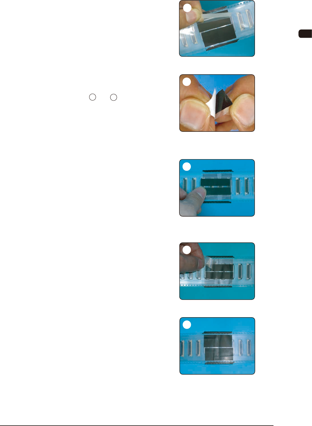
Peel off the transparent lm.
Peel off the white peeling paper on
the splicing tape which has been cut
in Step 1 and 7 .
Adhere two tapes to the rear side
(embossed bottom surface) of the
cover tape so that the joint position is
located at the center.
Peel off the transparent lm.
Conrm that the splicing tape has
been adhered securely to the cover
tape and the carrier tape surfaces.
When the tape has been spliced
securely, the procedure is completed.
13
14
15
11
12
OM-1606
6-38
6. Splicing
0908-001
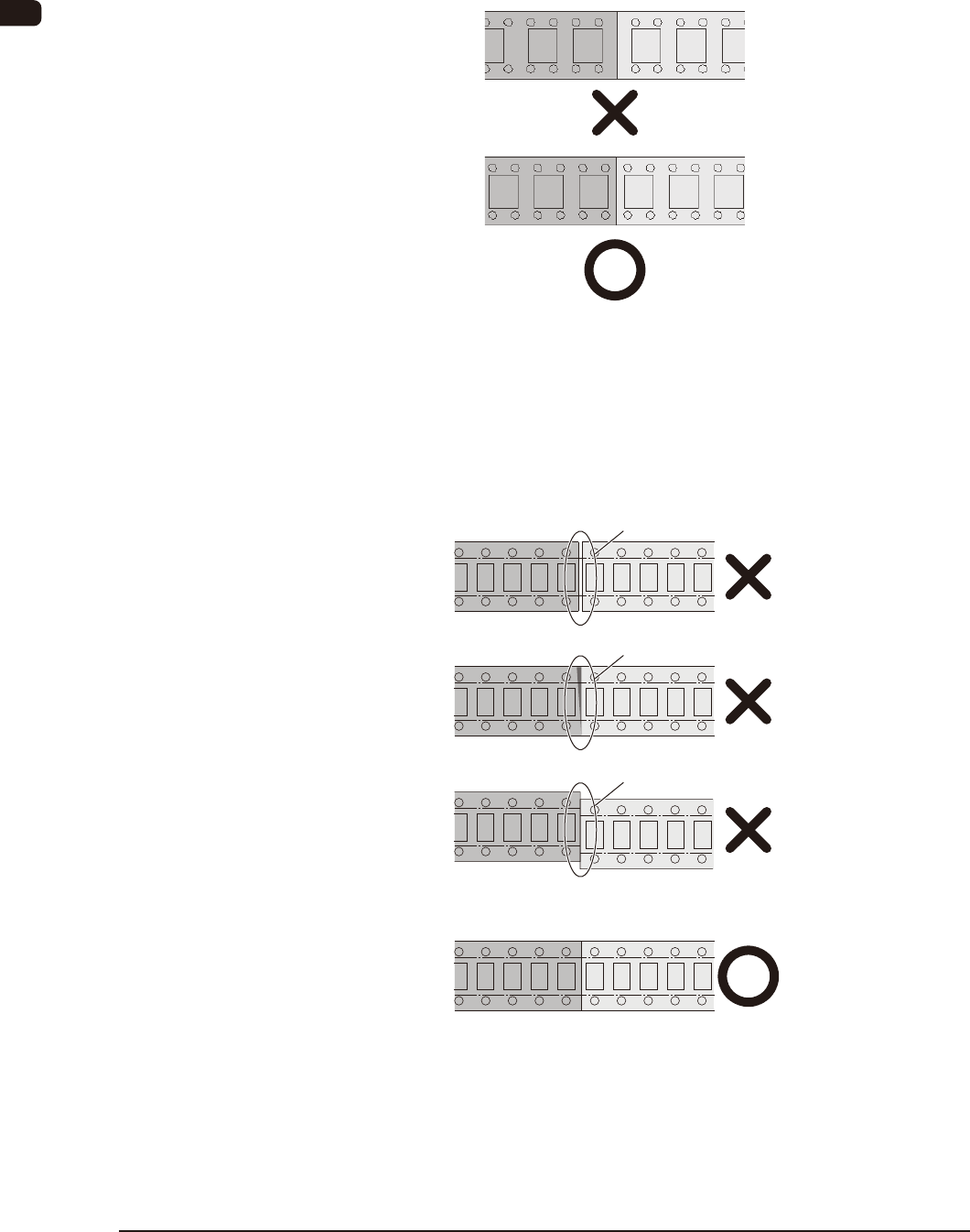
6.9.4 Precautions
(1) When the carrier tape is cut or spliced, take care so that the
component feed pitch does not slide.
Otherwise, the pick-up error might occur.
(2) Cut and splice the carrier tape so that there is no gap, overlap or
deviation of the carrier tape on the joint position.
Cut the tape at an angle of 90 degrees to the long side and at the
same position, based on the sprocket hole.
If there is any gap, overlap or deviation, a feed error might occur.
Gap
Overlap
Deviation