OM-1606-006w_GT-28x.pdf - 第144页
OM-1606 6-42 6. Splicing 6.10.3 Cutting T ape on Feeder Side (1) Prepare the tape on the feeder side. (2) Cut the tape, using the tape cutting jig. Set the tape on the pilot pins and cut it. The tape cut jig is used for …
OM-1606
6. Splicing
6-411005-002
•
In the case of 12 mm, 20 mm, 28 mm or 36 mm pitch, the pilot pin is
not to be used.
•
Take care not to cut any component in order to prevent damage to the
tape cutting jig.
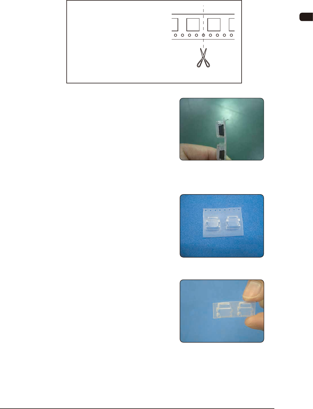
In the case of 12 mm, 20 mm, 28 mm
or 36 mm pitch, cut off the carrier tape
with pockets so that the center of a
carrier pocket is cut without using the
pilot pin.
Cut it so that any overlap of the tape is
not caused in the joint section.
Cut Position
(3) The preparation of new tape has
been completed.
6.10.2 Preparation of Carrier Tape for Joint
(1) Cut off the carrier tape so that it has
two pockets, which has been cut off
from a new tape.
(2) Cut it off at the position close to the
border of the pocket.
OM-1606
6-42
6. Splicing
6.10.3 Cutting Tape on Feeder Side
(1) Prepare the tape on the feeder side.
(2) Cut the tape, using the tape cutting
jig.
Set the tape on the pilot pins and cut
it.
The tape cut jig is used for the tapes
up to the 32 mm width. For the 44
mm, 56 mm width tape, cut the tape
by two stages.
•
For the tape with the width of 72 or
88 mm, cut it using commercially
available scissors with a blade long
length enough to cut the tape all at
once, so that the cut position does
not deviate.
In the case of 12 mm, 20 mm, 28 mm
or 36 mm pitch, the pilot pin is not to
be used.
•
Take care not to cut any component
in order to prevent damage to the
tape cutting jig.
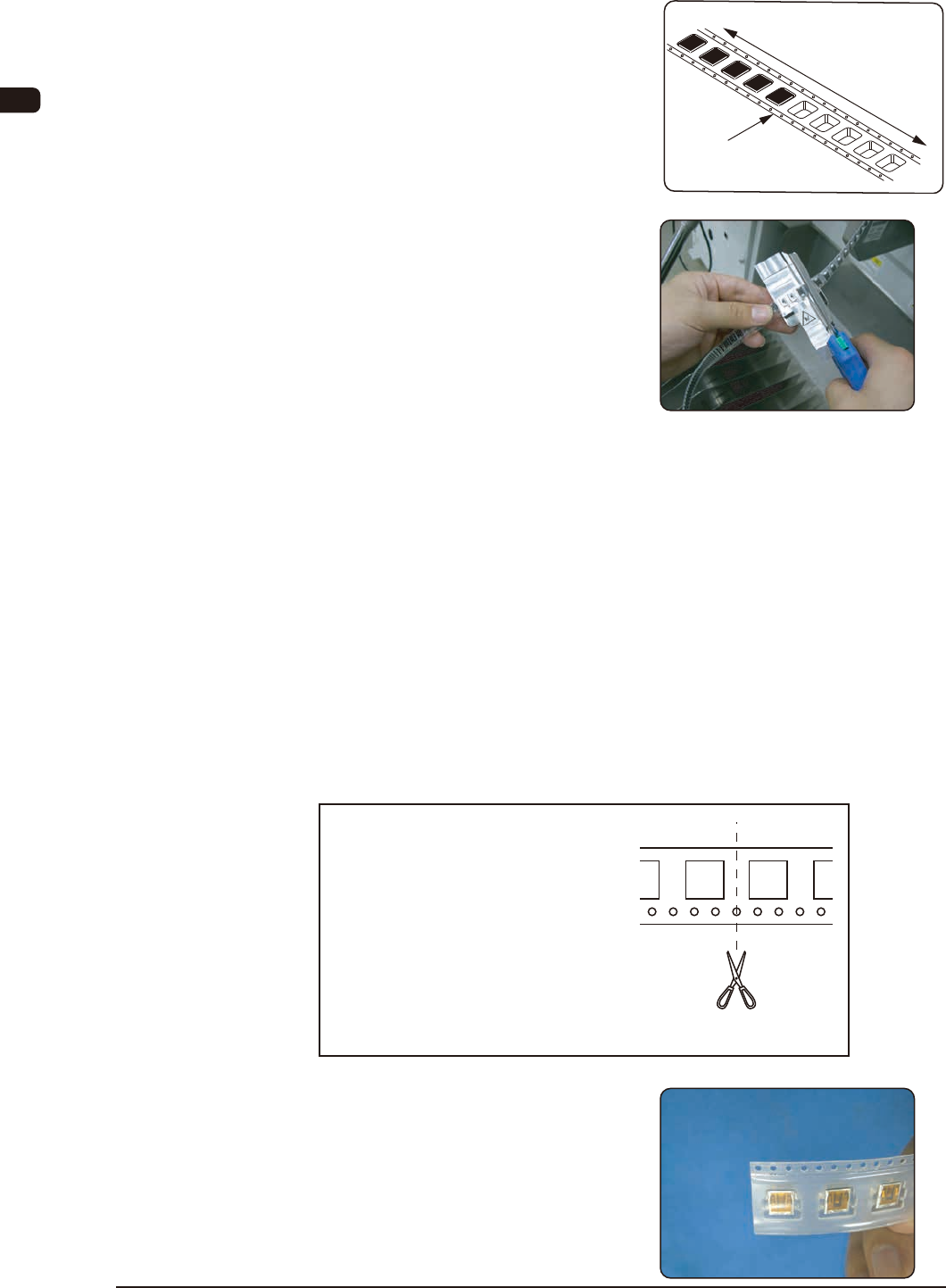
In the case of 12 mm, 20 mm, 28 mm
or 36 mm pitch, cut off the carrier tape
with pockets so that the center of a car-
rier pocket is cut without using the pilot
pin.
Cut it so that any overlap of the tape is
not caused in the joint section.
Cut Position
(3) The preparation of the tape on the
feeder side has been completed.
If it tends to bend, correct it.
1005-002
Feeder Side
Section where the
components are
not included
Section where the
components are included
Cut Position
OM-1606
6. Splicing
6-43
6.10.4 Tape Splicing Procedure
Note
When part of black tape is left on the peeling paper, return the peeling
paper and press the tape against the paper. Then, peel off the peeling paper
again.
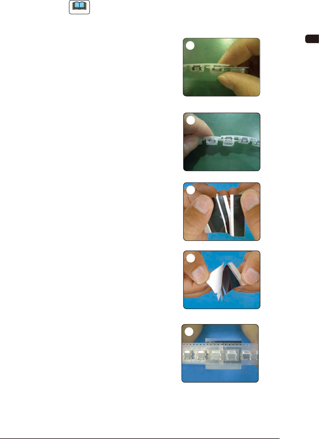
Cover the prepared carrier tape for
joint over the head pocket on the
new tape and insert it to the end of
the pocket.
If it can not be inserted easily,
change the direction of the tape for
joint.
Cover also the tape on the feeder
side over the head pocket and insert
it to the end of the pocket.
At that time, the cover tape on the
side of the new tape should be above
the tape on the side of the feeder.
In the case of the tape with 24,
32, 44, 56, 72 and 88 mm width,
cut off the splicing tape along the
perforations.
The cut tape is not to be used.
Peel off the white peeling paper on
the splicing tape.
In the case of the tape with 32,
44, 56, 72 and 88 mm width, peel
the white peeling paper up to the
perforations and bend it.
Align the reference guide with the
tape border on the opposite side of
the sprocket hole and afx the tape
so that the joint position is at the
center.
In the case of the tape with 32, 44,
56, 72 and 88 mm width, align the
bent perforation section with the tape
border on the sprocket hole side and
afx it.
1005-002
1
2
4
3
5