OM-1606-006w_GT-28x.pdf - 第161页
OM-1606 7-1 1 7. Maintenance 7.4.6 T ape Feed Gear Section Worm Gear Every Three Months Cleaning, Lubrication Remove the dust protective cover and remove dust and debris using a cloth or bamboo probe. Then, apply MOLYNOC…
OM-1606
7-10
7. Maintenance
7.4.5 Joint Detection Unit
Tape Guide on the Joint Detection Unit
(Only for GD-28080, GD-28081, GD-28082,
GD-28083, GD-12162, GD-24322, GD-44562,
GD-72002 and GD-88002)
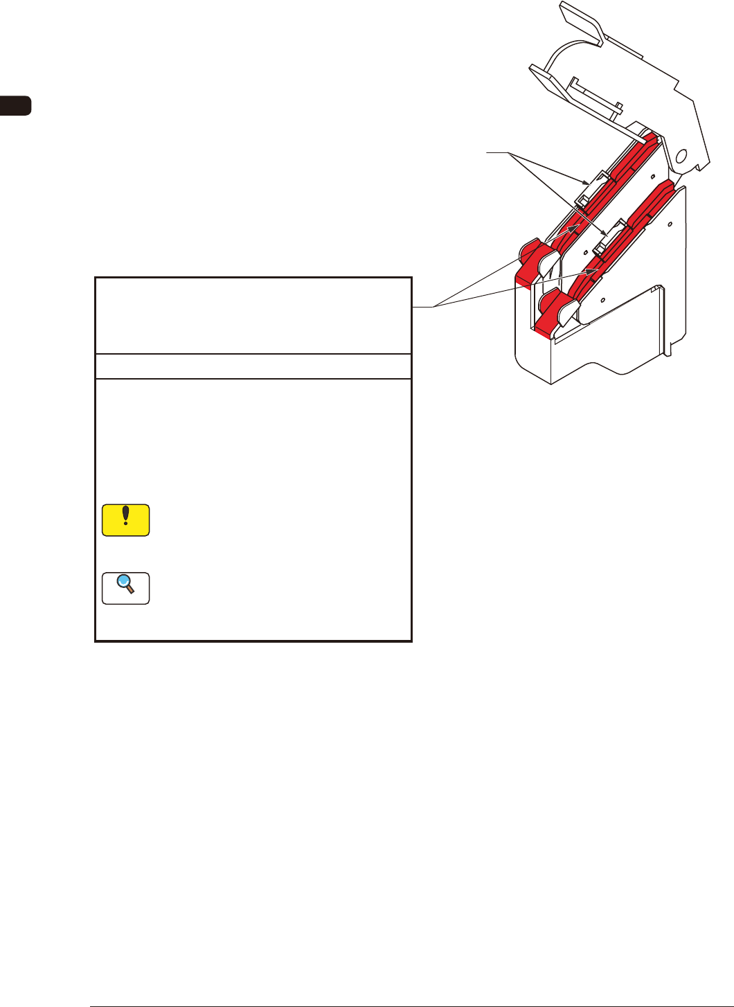
Every week Cleaning
• For GD-28080, GD-28081, GD-28082 or
GD-28083, lift the cover and remove any alien
substance using the applicator or bamboo probe.
•
If any foreign substance is attached
when the tape is passed through,
it might damage the joint detection
sensor or cause a tape feeding error.
In the case of GD-28080, GD-28081,
GD-28082 or GD-28083
Sensor Section
Refer to "7.5.2 8 mm Dual Feeder
Joint Detection Unit Sensor Section
Cleaning (For GD28080, D-28081,
GD-28082 or GD-28083) " for details.
For GD-12162, GD-24322, GD-44562, GD-72002
or GD-88002, remove any alien substance from
under the joint detection unit, using the applicator
or bamboo probe.
Reference
Notice
FG9
1011-002
OM-1606
7-11
7. Maintenance
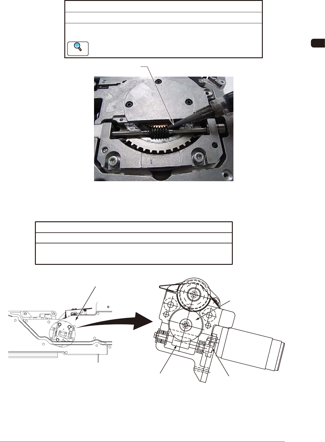
7.4.6 Tape Feed Gear Section
Worm Gear
Every Three Months Cleaning, Lubrication
Remove the dust protective cover and remove dust and debris using a cloth
or bamboo probe. Then, apply MOLYNOC Grease AP1 using the greasing jig.
Greasing Jig
Refer to "7.5.1 How to Apply Grease to the Sprocket Driving Gear
Unit" for details.
Reference
FG10
7.4.7 Cover Tape Take-up Gear Section
Flat End Wheel, Worm Gear, Worm Wheel (Right Side, Left Side)
Every Three Months Cleaning, Lubrication
Remove the cover and remove dust and debris using a cloth or bamboo probe.
Then, apply MOLYNOC Grease AP1 using the greasing jig.
Flat End Wheel
Worm Gear
The illustration shows the left side of the unit.
However, apply the same procedure also
to the right side of the unit.
Worm Wheel
Cover
FG11
0908-001
OM-1606
7-12
7. Maintenance
7.5 Maintenance Method
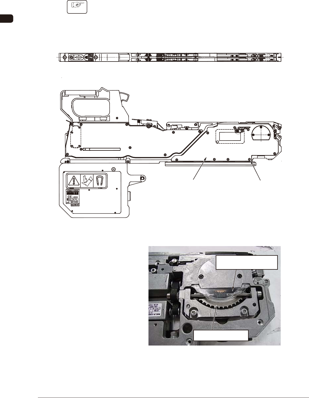
7.5.1 How to Apply Grease to the Sprocket Driving Gear Unit
Procedure
(1) Open the right side cover.
Remove the set screw (countersunk head screw) on 7 locations and open the
right side cover to expose the right sprocket.
In the right sprocket section, the dust preventive cover made of transparent
resin is attached as shown in the following gure.
Right Sprocket
Dust Preventive Cover
(Transparent)
Right Side Cover Set Screw
(Countersunk Head Screw)
on 7 locations
FG12
0908-001