OM-1606-006w_GT-28x.pdf - 第167页
OM-1606 7-17 7. Maintenance (2) Clean the sensor section. • Debris Removal When any debris such as sticky substance, is stuck, rub it off using a bamboo probe. Sticky Substance FG21 • Wiping Dirt Off Insert a cotton appl…
OM-1606
7-16
7. Maintenance
7.5.2 8 mm Dual Feeder Joint Detection Unit Sensor Section Cleaning
(GD-28080, GD-28081, GD-28082, GD-28083)
7.5.2.1 Spots to be Cleaned
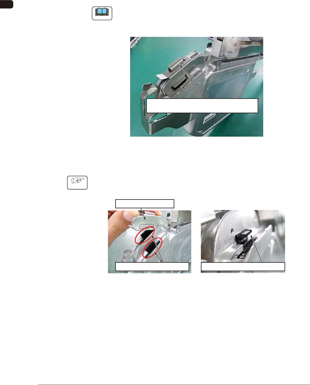
Clean dust and debris stuck to the sensor section inside the joint detection unit.
There is one sensor section each on the right and left lanes. Clean both of them.
Note
Without cleaning, the sensor does not function normally and an error might be
caused in the detection of spliced joint (When dust is attached, the machine
might be in the condition where it is always detecting the spliced joint).
Sensor Section
(One Location each on the Right and Left)
FG19
7.5.2.2 How to Clean the Sensor Section
Procedure
(1) Lift the tape holding cover to expose the sensor, and clean the gap in the
sensor section.
Expose the Sensor Section.
Clean the Gap in the Sensor Section.
Tape Holding Cover
FG20
0908-001
OM-1606
7-17
7. Maintenance
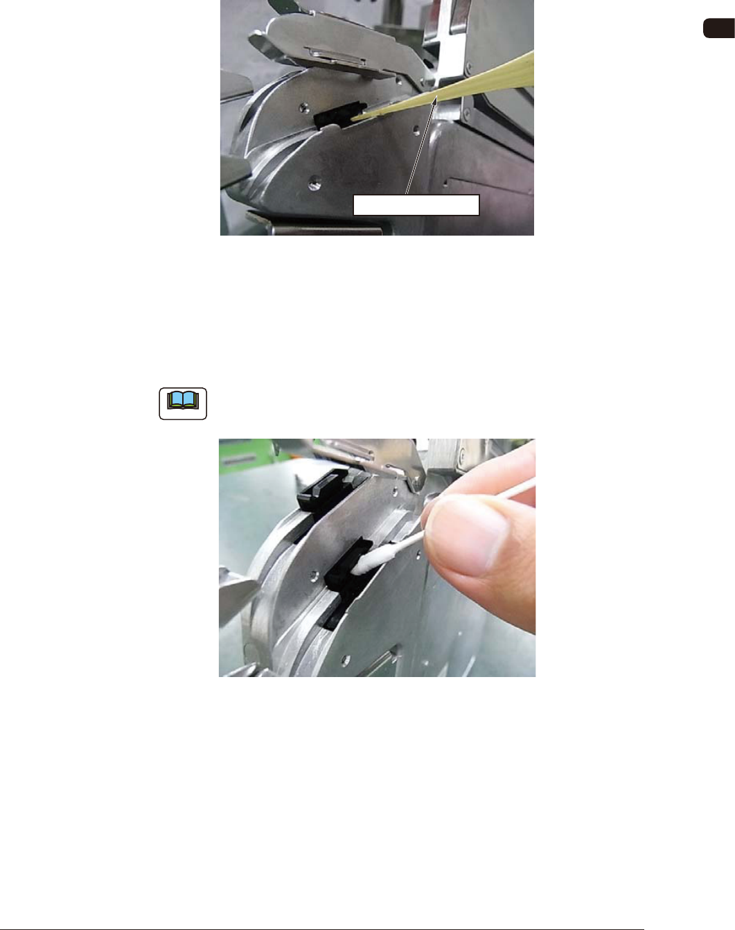
(2) Clean the sensor section.
•
Debris Removal
When any debris such as sticky substance, is stuck, rub it off using a bamboo
probe.
Sticky Substance
FG21
•
Wiping Dirt Off
Insert a cotton applicator dipped in alcohol into the gap in the sensor section
to clean any dirt by rubbing. After cleaning the dirt by rubbing, rub it using a
dry cotton applicator.
Note
FG 22 shows the right lane cleaning work.
The same procedure is applied to the left lane cleaning work.
FG22
0908-001
OM-1606
7-18
7. Maintenance
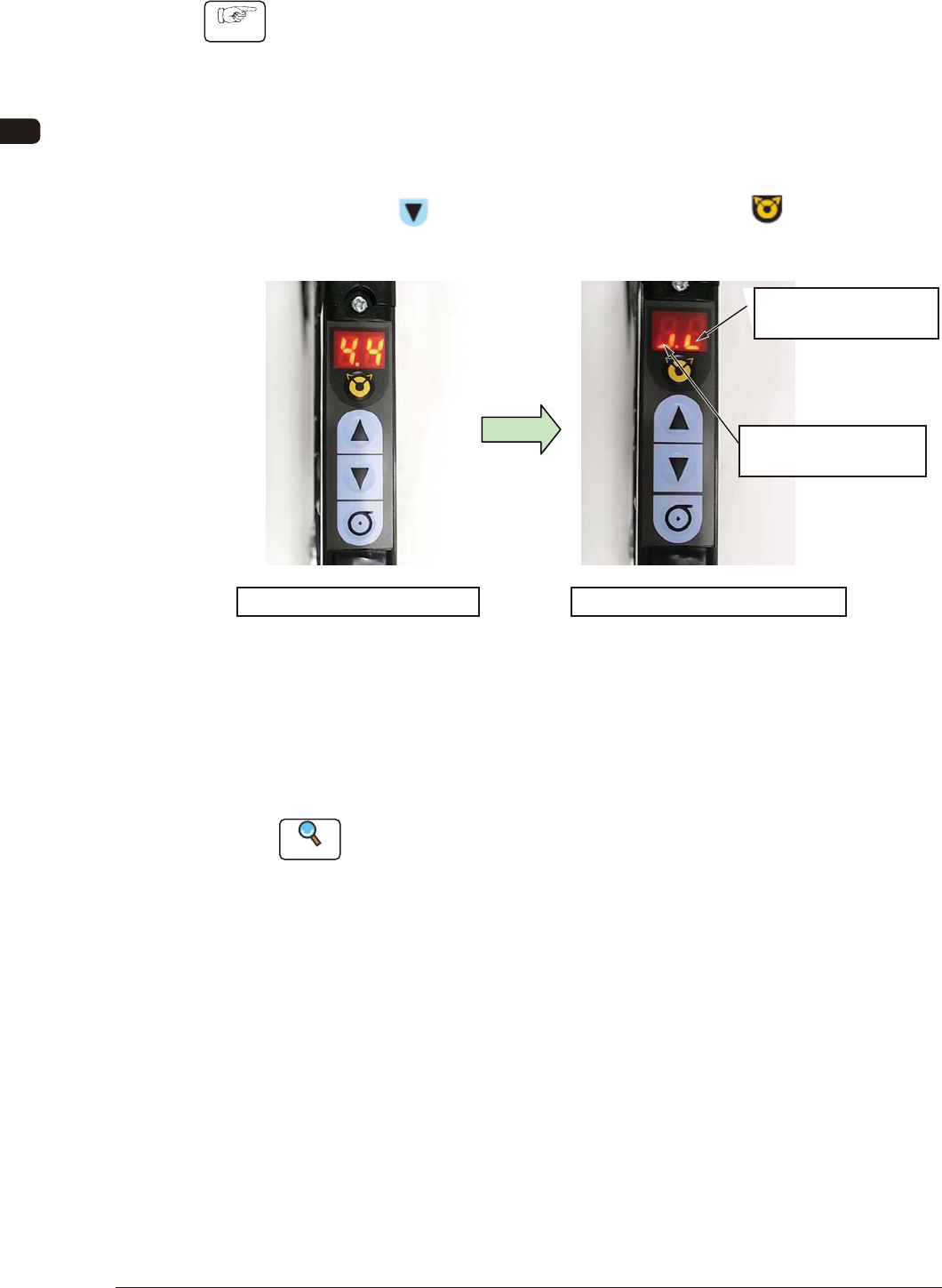
7.5.2.3 Sensor Detection Check
Procedure
(1) Check the sensor detection.
The sensor I/O status can be checked in the digital display section on the
operation panel.
Turn ON the power to the tape feeder and perform the following operations
to check the sensor status.
•
Sensor I/O Status Display Mode Change
Press the
button and within 2 seconds, press the button. Keep
this condition (two buttons are being pressed) for 2 seconds.
Normal Mode Panel Display
Sensor I/O Status Display Mode
It shows the Lane 1
Sensor Status.
It shows the Lane 2
Sensor Status.
Mode Change
FG23
When the mode is changed to the Sensor I/O Status Display Mode, the
lighting display (ON Status) appears as shown in the upper right picture.
In the case that any dirt or debris is stuck to the sensor, or the sensor is
broken down, the display might be turned OFF (OFF Status).
Reference
Refer to "4.2.10 I/O Status Indication for Sensor, etc." for details.
0908-001