OM-1606-006w_GT-28x.pdf - 第170页
OM-1606 7-20 7. Maintenance 7.5.3 Wide Feeder Joint Detection Unit Sensor Section Cleaning (GD-12162, GD-24322, GD-44562, GD-72002, GD-88002) Procedure (1) Remove the set screws and side cover on the joint detection unit…
OM-1606
7-19
7. Maintenance
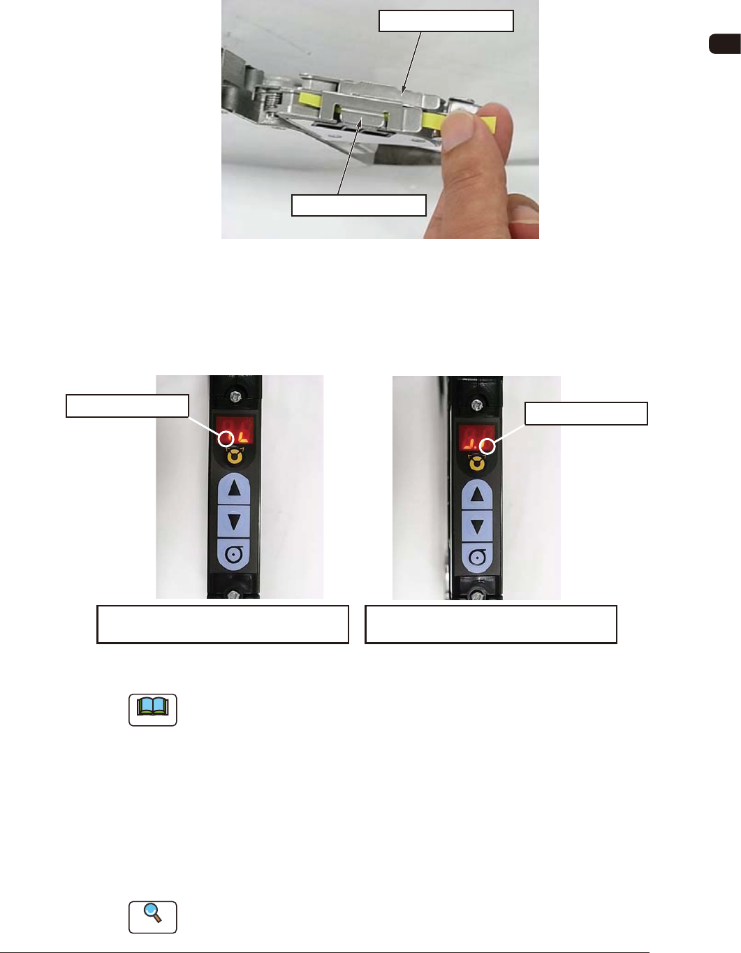
(2) Check the sensor detection status.
Shield the sensor from the light and check that the sensor detection is normal.
Pass a thin paper through the sensor section in the joint detection unit to
shield the sensor from the light.
On the Lane 1 Side
On the Lane 2 Side
FG24
When the sensor is normal, the status in the display section becomes ON to
OFF status. When this is conrmed, it is regarded that the joint detection
sensor functions normally.
Panel Display in Shielding the Sensor
on the Lane 2 Side from the Light
ON to OFF Status
ON to OFF Status
Panel Display in Shielding the Sensor
on the Lane 1 Side from the Light
FG25
Note
Make sure to check both sensors on the Lane 1 and Lane 2 sides.
(3) End the sensor I/O status display mode.
There are two mode ending procedures as follows.
Procedure 1
: Turn off the power to the tape feeder. When the power is
turned ON again, the mode is returned to the normal mode.
Procedure 2
: Perform the same procedure as the mode changing operation
to sensor I/O status mode.
Reference
Refer to "4.2.10 I/O Status Indication for Sensor, etc." for details.
0908-001
OM-1606
7-20
7. Maintenance
7.5.3 Wide Feeder Joint Detection Unit Sensor Section Cleaning
(GD-12162, GD-24322, GD-44562, GD-72002, GD-88002)
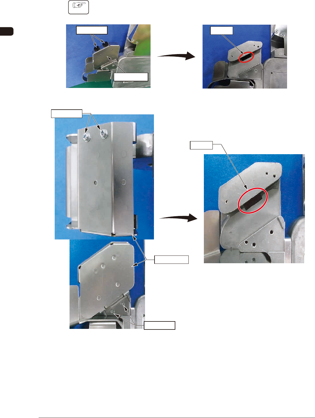
Procedure
(1) Remove the set screws and side cover on the joint detection unit to expose
the sensor section.
Set Screw
Sensor
After the removal
Side Cover
GD-12162, GD-24322, GD-44562 FG26
Set Screw
Set Screw
Sensor
After the removal
Side Cover
GD-72002, GD-88002 FG26-1
1011-002
OM-1606
7-21
7. Maintenance
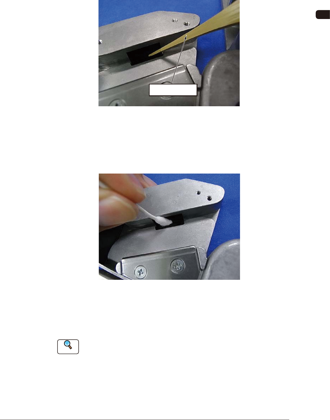
(2) Clean the sensor section.
•
Debris Removal Operation
When any debris such as sticky substance, is stuck, rub it off using a bamboo
probe.
Bamboo Prove
FG27
•
Wiping Dirt Off
Insert a cotton applicator dipped in alcohol into the gap in the sensor section
to clean any dirt by rubbing. After cleaning the dirt by rubbing, rub it using a
dry cotton applicator.
FG28
(3) Check the sensor detection.
Using the same procedure for the 8 mm dual feeder, check the sensor
detection status.
Reference
Refer to "7.5.2.3 Sensor Detection Check" for details.
1011-002