OM-1606-006w_GT-28x.pdf - 第212页
OM-1606 9-3 9. Reference T aping Specications 9.6 Strength of Carrier and Cover T apes Carrier Tape When a tensile force of 10 N (1.02 kgf) is applied in the direction of unreeling the tape, the tape shall withstand thi…
OM-1606
9-2
9. Reference Taping Specications
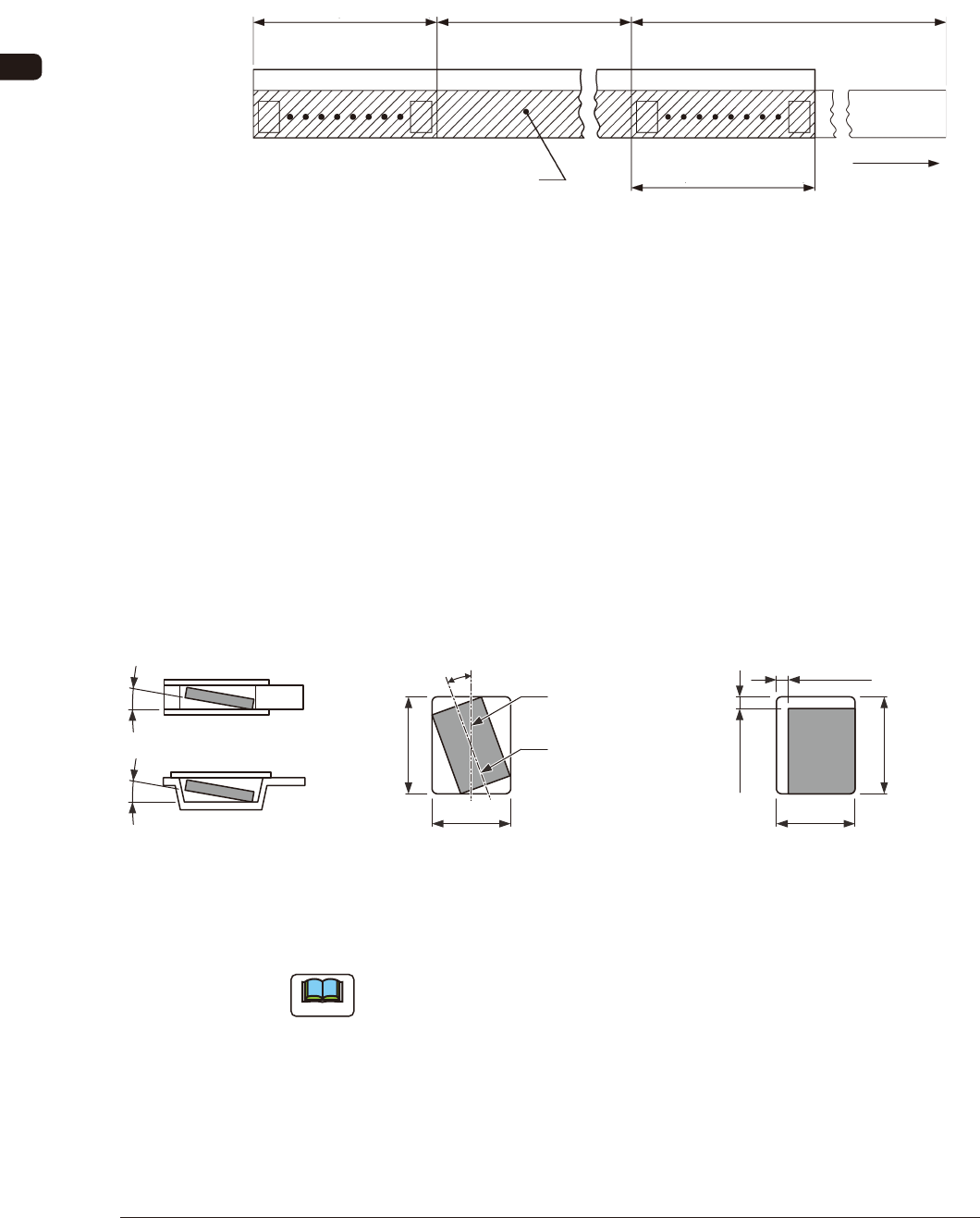
9.3 Leader Section (Tape End Section)
The tape length in the leader section should be 400 mm or more including the
empty component compartment. Such empty component compartment should be
sealed with a cover tape for 100 mm or more.
Trailer (160 mm min.)
Portion Equipped with Surface
Mounting Component
Leader (400 mm min.)
Cover Tape
Empty Component
Compartment
Empty Component
Compartment
(100 mm min. Seal)
Direction of Unreeling
FI3
9.4 Trailer Section (Tape Trailer Section)
The tape length of the trailer section should be 160 mm or more including the
empty component compartment.
The empty component compartment should be sealed with a cover tape.
The last portion of carrier tape shall release from the reel hub.
9.5 Position of Taped Component
B
0
Center Line of
Component Compartment
Center Line of
Component
(Note)
20° or less (Tape Width 8, 12 mm)
10° or less (Tape Width 16 mm min)
Top ViewSide Sectional View or
Front Sectional View
Component Revolution in
Horizontal Direction
Component Inclination
10° or less10° or less
B0
A0
(Note)
0.5 mm or less
(Tape Width 8 to 24 mm)
1.0 mm or less
(Tape Width 32 to 72 mm)
(Note)
0.5 mm or less
(Tape Width 8 to 24 mm)
1.0 mm or less
(Tape Width 32 to 72 mm)
Top View
Component Bias in
Horizontal Direction
A0
FI4
Note
When the direction of a component is changed in the square punched hole or
embossed tape hole, the component can not be picked up easily. In such case,
keep an appropriate clearance around the component in the hole.
0908-001
OM-1606
9-3
9. Reference Taping Specications
9.6 Strength of Carrier and Cover Tapes
Carrier Tape
When a tensile force of 10 N (1.02 kgf) is applied in the direction of unreeling
the tape, the tape shall withstand this force.
Cover Tape
When a tensile force of 10 N (1.02 kgf) is applied to the tape, the tape shall
withstand this force.
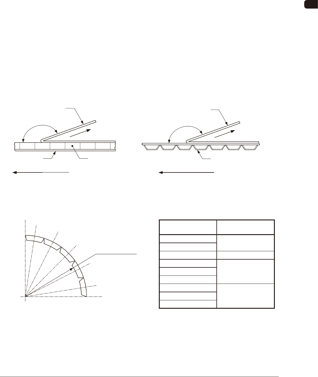
9.7 Peel Strength of Cover Tape
The direction of the cover tape peeling force should be maintained at an angle of
165 to 180 degrees.
When the cover tape is peeled off at the speed of 300 mm/min ± 10 mm/min, the
cover tape peeling force should be 0.1 to 0.7 N (10.2 to 71.4 gf).
Rectangle Hole Punched Carrier Type Taping Embossed Carrier Type Taping
Cover Tape
Direction of Peel off
Rectangle Hole
Punched Carrier Tape
Bottom Cover Tape
Direction of Unreeling
165° to 180°
Cover Tape
Direction of Peel off
Direction of Unreeling
Embossed Carrier Tape
165° to 180°
Angle in Peel Test FI5 Angle in Peel Test FI6
9.8 Minimum Bending Radius
1005-002
Minimum Bending Radius FI7
Width of Tape and Minimum Bending Radius
Width of Tape
(mm)
Minimum Bending
Radius (mm)
8
30
12
16 40
24
5032
44
56
7572
88
When the tape is bent with the minimum bending radius, the tape shall not be
damaged, the components shall maintain their position and direction in the tape
and shall be free from abnormalities such as damage.
TI1
Minimum Bending
Radius (R)
OM-1606
9-4
9. Reference Taping Specications
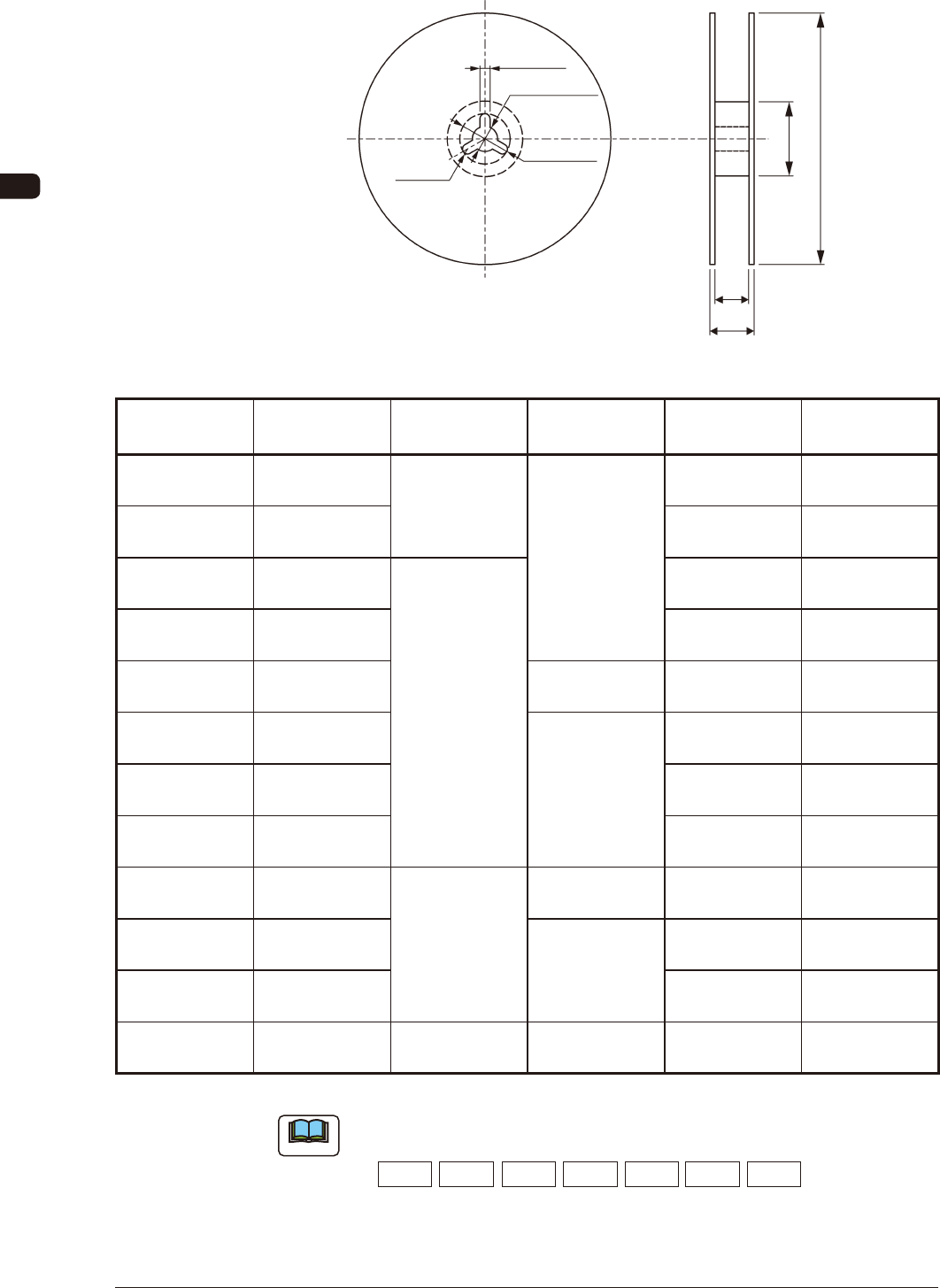
9.9 Style and Dimensions of Reel
2.0 ± 0.5
13.0 ± 0.2
21 ± 0.8
R 1.0
N A
W1
W2
Unit : mm
FI8
Classication
Symbol of Reel
Applicable
Tape Width
A N W
1
W
2
R 08 A
8
178
60 or more
8.4
+2
0
14.4 or less
R 12 A
12
12.4
+2
0
18.4 or less
R 08 □ 8
180 to 382
8.4
+2
0
14.4 or less
R 12 □ 12 12.4
+2
0
18.4 or less
R 16 □ 16 80 or more 16.4
+2
0
22.4 or less
R 24 □ 24
100 or more
24.4
+2
0
30.4 or less
R 32 □ 32 32.4
+2
0
38.4 or less
R 44 □ 44 44.4
+2
0
50.4 or less
R 56 □ 56
382
150 or more 56.4
+2
0
62.4 or less
R 72 □ 72
Note (c)
72.4
+2
0
89.0 or less
R 88 □ 88 88.4
+2
0
105.0 or less
R 04 B 4 180 60 or more 4.3
+2
0
7.95 or less
Unit : mm
TI2
Note
(a) An English capital letter given below which corresponds to nominal value
of dimension A is entered into □ in classication symbol of reel.
A:178 B:180 C:254 D:330 E:360 F:370 G:382
(b) Dimension W
2
means overall thickness of the reel.
(c) The tape including components should be taken up around the hub without
any damage.
1011-003