OM-1606-006w_GT-28x.pdf - 第214页
OM-1606 10-1 10. Electrical Circuit Diagrams 0908-001 A(M804WW ---3001) 10. Electrical Circuit Diagrams 10.1 Feeder Control Circuit Diagram (GT -28080 / GT -28082) Drawer Connector Connection Confirmation Signal Lane 1 F…
OM-1606
9-4
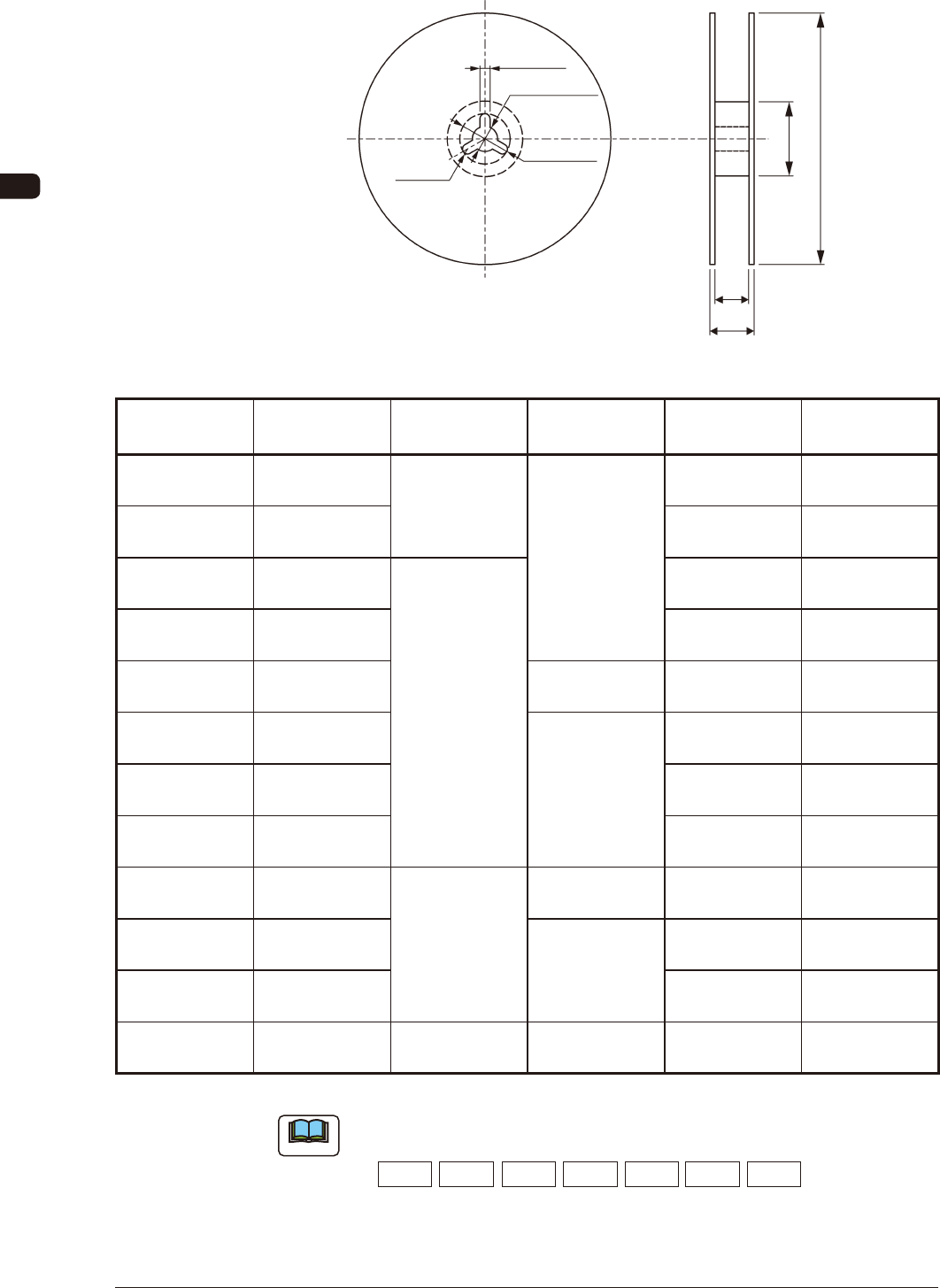
9. Reference Taping Specications
9.9 Style and Dimensions of Reel
2.0 ± 0.5
13.0 ± 0.2
21 ± 0.8
R 1.0
N A
W1
W2
Unit : mm
FI8
Classication
Symbol of Reel
Applicable
Tape Width
A N W
1
W
2
R 08 A
8
178
60 or more
8.4
+2
0
14.4 or less
R 12 A
12
12.4
+2
0
18.4 or less
R 08 □ 8
180 to 382
8.4
+2
0
14.4 or less
R 12 □ 12 12.4
+2
0
18.4 or less
R 16 □ 16 80 or more 16.4
+2
0
22.4 or less
R 24 □ 24
100 or more
24.4
+2
0
30.4 or less
R 32 □ 32 32.4
+2
0
38.4 or less
R 44 □ 44 44.4
+2
0
50.4 or less
R 56 □ 56
382
150 or more 56.4
+2
0
62.4 or less
R 72 □ 72
Note (c)
72.4
+2
0
89.0 or less
R 88 □ 88 88.4
+2
0
105.0 or less
R 04 B 4 180 60 or more 4.3
+2
0
7.95 or less
Unit : mm
TI2
Note
(a) An English capital letter given below which corresponds to nominal value
of dimension A is entered into □ in classication symbol of reel.
A:178 B:180 C:254 D:330 E:360 F:370 G:382
(b) Dimension W
2
means overall thickness of the reel.
(c) The tape including components should be taken up around the hub without
any damage.
1011-003
OM-1606
10-1
10. Electrical Circuit Diagrams
0908-001 A(M804WW---3001)
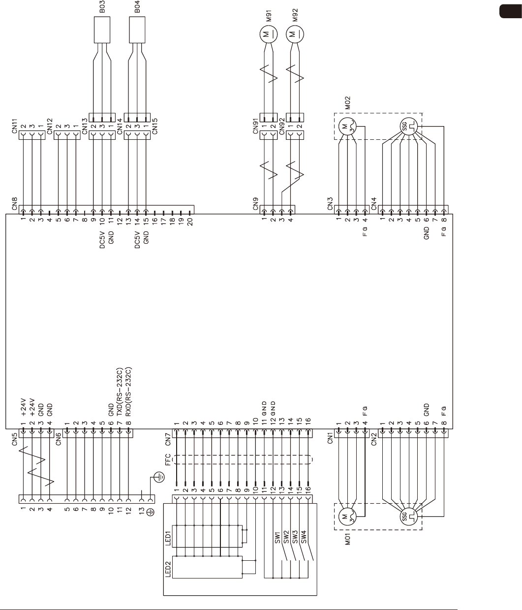
10. Electrical Circuit Diagrams
10.1 Feeder Control Circuit Diagram
(GT-28080 / GT-28082)
Drawer Connector
Connection Confirmation Signal
Lane 1 Feed Command
Lane 2 Feed Command
READY Signal
Connection Confirmation Signal
Lane 2 Tension Detection Sensor
Lane 1 Tension Detection Sensor
White
Brown
Blue
White
Brown
Blue
Blue
Black
Blue
Black
Blue
Black
Blue
Black
Blue
Black
Blue
Blue
Black
Blue
Blue
Black
Blue
Blue
Black
Blue
Operation Panel
Cover Tape Take-up Key
7-Segment LED is turned ON (a)
7-Segment LED is turned ON (b)
7-Segment LED is turned ON (c)
7-Segment LED is turned ON (d)
7-Segment LED is turned ON (e)
7-Segment LED is turned ON (f)
7-Segment LED is turned ON (g)
7-Segment LED is turned ON (D.P)
For Dynamic Light ON (first figure)
For Dynamic Light ON (second figure)
Lane Selection Key
Forward Key
Backward Key
DC Motor No. 2 Power Supply
DC Motor No. 1
DC Motor No. 1 Power Supply
DC Motor No. 2
Lane 1 Take-up Motor
Lane 2 Take-up Motor
Lane 1 Servo Motor
Motor No. 1 Phase W
Motor No. 1 Phase U
Motor No. 1 Phase V
Reserve
Encoder No. 1 Phase A
/Encoder No. 1 Phase A
Encoder No. 1 Phase B
Power Supply (DC5V)
/Encoder No. 1 Phase B
Motor No. 2 Phase W
Motor No. 2 Phase U
Motor No. 2 Phase V
Lane 2 Servo Motor
Reserve
Encoder No. 2 Phase A
/Encoder No. 2 Phase A
Encoder No. 2 Phase B
/Encoder No. 2 Phase B
Power Supply (DC5V)
Feeder Control Amplifier
OM-1606
10-2
10. Electrical Circuit Diagrams
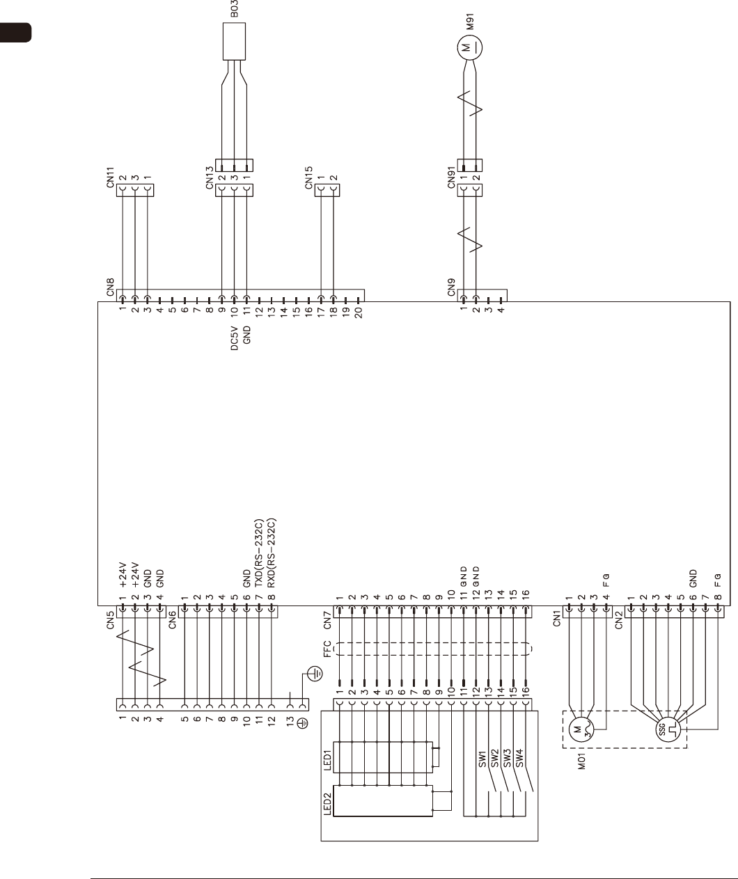
10.2 Feeder Control Circuit Diagram (GT-12162)
0908-001 -(M804WG---1001)
Drawer Connector
Connection Confirmation Signal
Lane 1 Feed Command
Lane 2 Feed Command
READY Signal
Connection Confirmation Signal Lane Tension Detection Sensor
White
Brown
Blue
Blue
Black
Blue
Black
Blue
Black
Blue
Black
Blue
Blue
Black
Blue
Operation Panel
Cover Tape Take-up Key
7-Segment LED is turned ON (a)
7-Segment LED is turned ON (b)
7-Segment LED is turned ON (c)
7-Segment LED is turned ON (d)
7-Segment LED is turned ON (e)
7-Segment LED is turned ON (f)
7-Segment LED is turned ON (g)
7-Segment LED is turned ON (D.P)
For Dynamic Light ON (first figure)
For Dynamic Light ON (second figure)
Lane Selection Key
Forward Key
Backward Key
DC Motor
DC Motor Power Supply
Lane Take-up Motor
Lane Servo Motor
Motor Phase W
Motor Phase U
Motor Phase V
Reserve
Encoder Phase A
/Encoder Phase A
Encoder Phase B
Power Supply (DC5V)
/Encoder Phase B
Feeder Control Amplifier