OM-1606-006w_GT-28x.pdf - 第33页
OM-1606 2. Attachment and Detachment of T ape 2-1 2. Attachment and Detachment of T ape 2.1 Attachment of Paper or Embossed T ape Procedure (1) While gently pressing the end of the suppressor with your nger , press the …

OM-1606
1-6
1. Scope
0908-001
[8] Clamp Release Lever
This button is pressed when the tape feeder is removed from the bank feeder
change cart.
[9] Operation Panel
Shows the various settings or status of the tape feeder.
Reference
Refer to "4. Operation Panel" for details.
[10] Connector
This connector conducts electricity and electrical signals.
[11] Barcode Label
Barcodes are printed for tape feeder model, serial No. and ACV system.
[12] Cover Tape Outlet Cover
This is the cover on the cover tape housing section.
This cover is opened when the cover tape is taken out from the cover tape
housing section.
Two units are attached onto the dual tape feeder with 8 mm width.
A single unit is attached onto the dual tape feeder with 12 mm width or
more.
[13] Cutter
This cutter cuts off the cover tape taken from the cover tape housing section.
[14] Magnetic Plate
It is attached to the chute section.
Using magnetic force, the component pick-up operation is stabilized.
It is attached only onto the dual tape feeder with 8 mm width or 12 mm
width.
[15] Magnetic Plate Housing Section
When the Magnetic Plate is not to be used, it is stored in this housing space.
It is attached only onto the dual tape feeder with 8 mm width or 12 mm
width.
OM-1606
2. Attachment and Detachment of Tape
2-1
2. Attachment and Detachment of Tape
2.1 Attachment of Paper or Embossed Tape
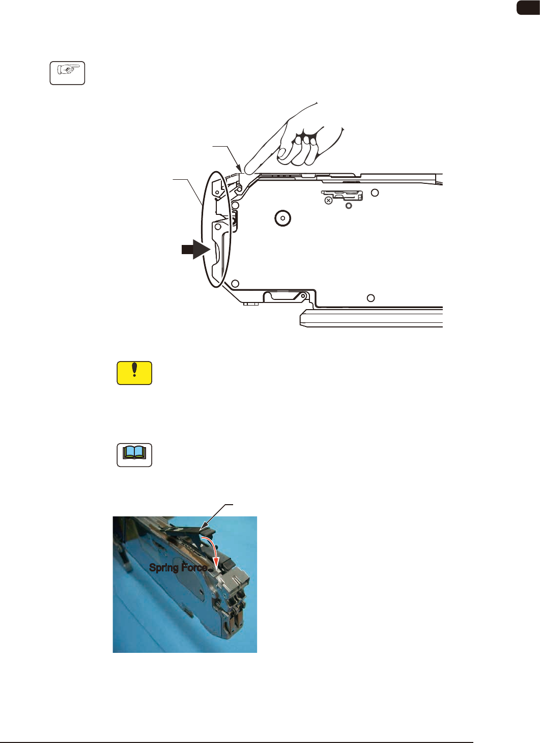
Procedure
(1) While gently pressing the end of the suppressor with your nger, press the
lower side of the front hook to lift the suppressor.
Front Hook
Suppressor
FB1
Notice
The suppressor is an important component which affects the pick-
up rate greatly.
If unnecessary stress works on the suppressor, such as dropping
the tape feeder, it might become deformed.
Take the greatest care in handling the suppressor.
Note
The suppressor is closed automatically with the spring force at the fulcrum
point when the hand is released from the suppressor.
Spring Force
Suppressor
Spring Force
• 8 mm Width Dual Feeder
When the suppressor is lifted to
the point where clicking sound
is heard, the upper section can
be locked.
• Feeders except for 8 mm Width
The locking mechanism is not
included. Keep the lifted
suppressor when the tape is set.
FB2
0908-001
OM-1606
2-2
2. Attachment and Detachment of Tape
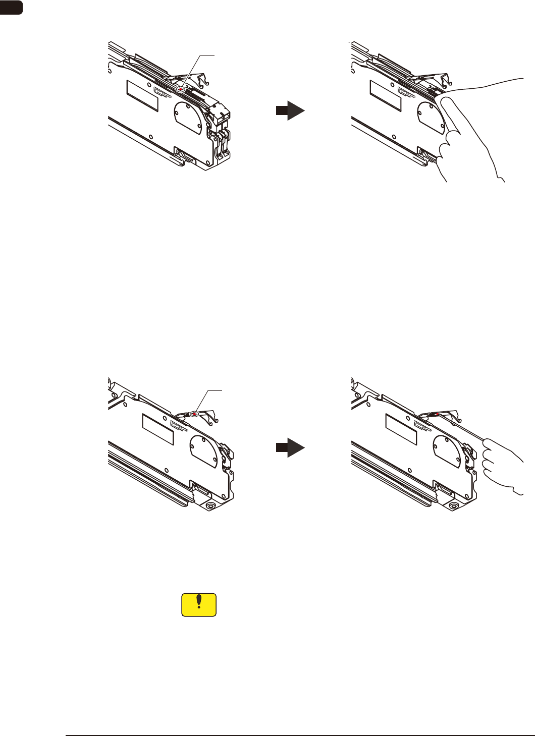
(2) Make sure there is no foreign substance (chip component or dust) on the
chute surface.
If there is any foreign substance on the chute surface, then remove it, using a
rag or air-blow.
Foreign Substance on the Chute Clean it
Chip Component
FB3
When the Magnetic Plate is used, clean it, because a component might be
attached to the magnetic plate.
(3) Make sure there is no foreign substance on the rear surface of the suppressor.
It is very easy for foreign substances to enter the corner section. Therefore,
check it carefully.
If any foreign substance, etc., is attached to the rear surface of the suppressor,
remove it with air-blow, tweezers, or thin bar.
Foreign Substance on the
Rear Surface of the Suppressor
Clean it
Chip Component
FB4
Notice
If the taping component is mounted with any foreign substance
attached, the suppresser might be deformed or a pick-up error
occur.
Therefore, clean it.
1005-002