OM-1606-006w_GT-28x.pdf - 第42页
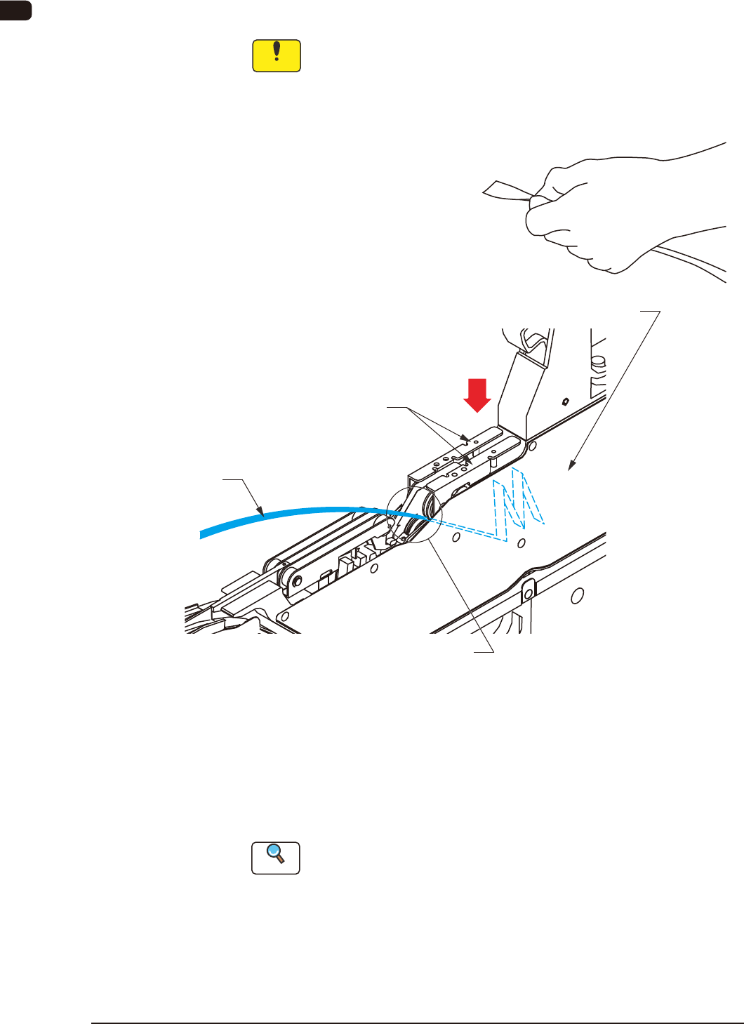
OM-1606 2-10 2. Attachment and Detachment of T ape (13) Press down the cover tape take-up release lever , insert the end of the cover tape into the cover tape housing section, and reset the cover tape take-up release lev…
OM-1606
2. Attachment and Detachment of Tape
2-9
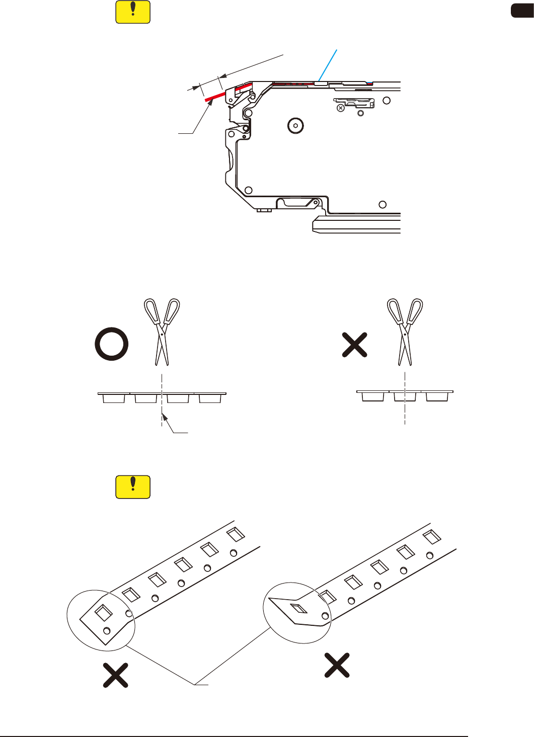
(12) Use scissors to cut the tape, so that the excess tape section is 5 to 10 mm.
Notice
Use scissors which would not cut ngers, and cut the tape one by
one.
Tape
5 to 10 mm
FB12
With wide embossed tape, avoid the embossed section when cutting the tape.
Cut it here.
FB13
Notice
When the tape is cut, do not fold the end section.
The tape might not be cut correctly by using the cutter attached to
the machine (SIGMA-G4/G5).
Folding
FB14
1005-002
OM-1606
2-10
2. Attachment and Detachment of Tape
(13) Press down the cover tape take-up release lever, insert the end of the cover
tape into the cover tape housing section, and reset the cover tape take-up
release lever.
Notice
•
It should be conrmed that there is not anything sticking, or any
twist or knot of the cover tape.
•
Take care so that your nger is not caught by the take-up gear.
Cover Tape Housing Section
Cover Tape Take-up Release Lever
Cover Tape
Hold the end of the cover tape between fingers
as shown in the figure and insert it into the cover tape
housing section.
Take-Up Gear Section
FB15
(14) Select the lane to be used using the lane selection button on the operation
panel and press the take-up button to send the cover tape to the cover tape
housing section.
Press the take-up button, continuously, until the take-up gear is stopped
automatically.
Reference
Refer to "4. Operation Panel" for operation panel.
0908-001

OM-1606
2. Attachment and Detachment of Tape
2-11
•
Cleaning of Suppressor Fulcrum Point
Chip components which scatter during the tape cassette setup operation and
enter inside the suppressor from the gap between the suppressor and the chute,
might be accumulated at the suppressor fulcrum point (between the chute under
the suppressor and the body).
Accumulated chip components around this area hinder the suppressor opening
or closing operation, so clean this area diligently.
Reference
Refer to "7.4.4 Component Discharging Section" for the details of
maintenance.
0908-001