OM-1606-006w_GT-28x.pdf - 第69页
OM-1606 2. Attachment and Detachment of T ape 2-37 1009-002 2.9 8 mm Cover T ape T ension Lever Section Spring Setup • Applicable Model : GT -28080 / 28081 / 28082 / 28083 • Cover T ape T ension Lever Section Spring Stan…
OM-1606
2-36
2. Attachment and Detachment of Tape
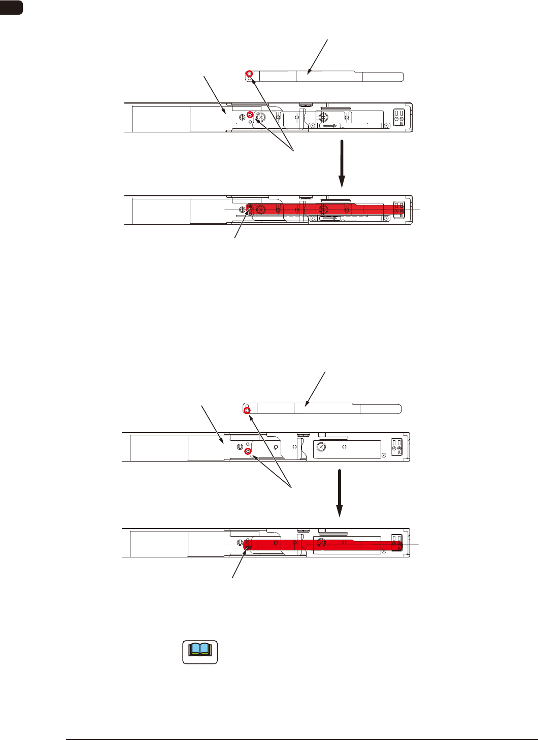
Magnetic Plate Attachment when the 12 mm Width Tape is used
Fix the magnetic plate with the set holes for 12 mm width tape aligned, so that
the magnetic plate is located at the center of the chute.
Chute Center Position
Set Hole Position
Set Screw
(Countersunk Head Screw)
Magnetic Plate
Chute section
FB46
Magnetic Plate Attachment when the 16 mm Width Tape is used
Fix the magnetic plate with the set holes for 16 mm width tape aligned, so that
the magnetic plate is located at the center of the chute.
Chute Center Position
Set Hole Position
Set Screw
(Countersunk Head Screw)
Magnetic Plate
Chute section
FB47
Note
After the use of the magnetic plate, remove it from the chute section and
house it in the magnet plate housing section.
When it is left after the removal, it might cause deformation or losing.
0908-001
OM-1606
2. Attachment and Detachment of Tape
2-371009-002
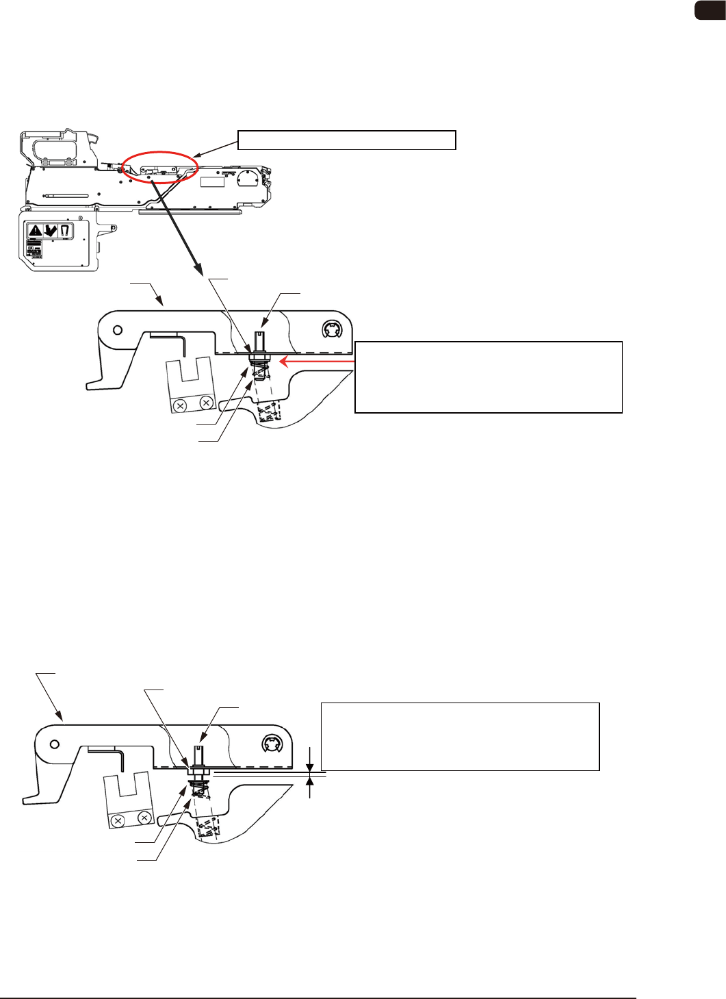
2.9 8 mm Cover Tape Tension Lever Section Spring Setup
•
Applicable Model : GT-28080 / 28081 / 28082 / 28083
•
Cover Tape Tension Lever Section Spring Standard Set Value
For the spring standard set values, the gap distance between the adjusting bolt
ange section and the hexagon nut should be "0 mm".
Tension Lever Section Spring Set Position
Standard Set Position:
Gap distance of "0 mm" between the flange
and hexagon nut
Cover Tape Tension Lever Section
Adjusting Bolt
Flange
Spring
Tension Lever
Hexagon Nut
Spring Standard Set Position FB48
•
Setting when a cover tape take-up error (E1 Error) occurs frequently
during the tape feeder operation
Depending on the cover tape type, the tape might not be taken up normally and
might be caught in the suppressor releasing section gap, in the case that the
spring has been set to "standard".
When this error occurs frequently, change the tension lever spring setting as
shown in the following gure.
Tension Lever Section Spring Set Position
Changed Position:
Gap distance of "1.7 mm" between the flange
and hexagon nut
Adjusting Bolt
Flange
Spring
Tension Lever
Hexagon Nut
Spring Changed Position FB48-1

OM-1606
2-38
2. Attachment and Detachment of Tape
1009-002
•
Adjusting Procedure
Procedure
(1) Loosen the hexagon nut.
(2) Turn the groove on the adjusting bolt ve times clockwise using a
screwdriver.
(When the bolt is turned around ve times from the standard position, the
gap distance between the ange and hexagon nut becomes "1.7 mm" and the
tape take-up strength becomes 1.4 times more of the standard strength.
(3) Return the hexagon nut to the upper surface position and x.