OM-1606-006w_GT-28x.pdf - 第70页
OM-1606 2-38 2. Attachment and Detachment of T ape 1009-002 • Adjusting Procedure Procedure (1) Loosen the hexagon nut. (2) Turn the groove on the adjusting bolt ve times clockwise using a screwdriver . (When the bolt i…
OM-1606
2. Attachment and Detachment of Tape
2-371009-002
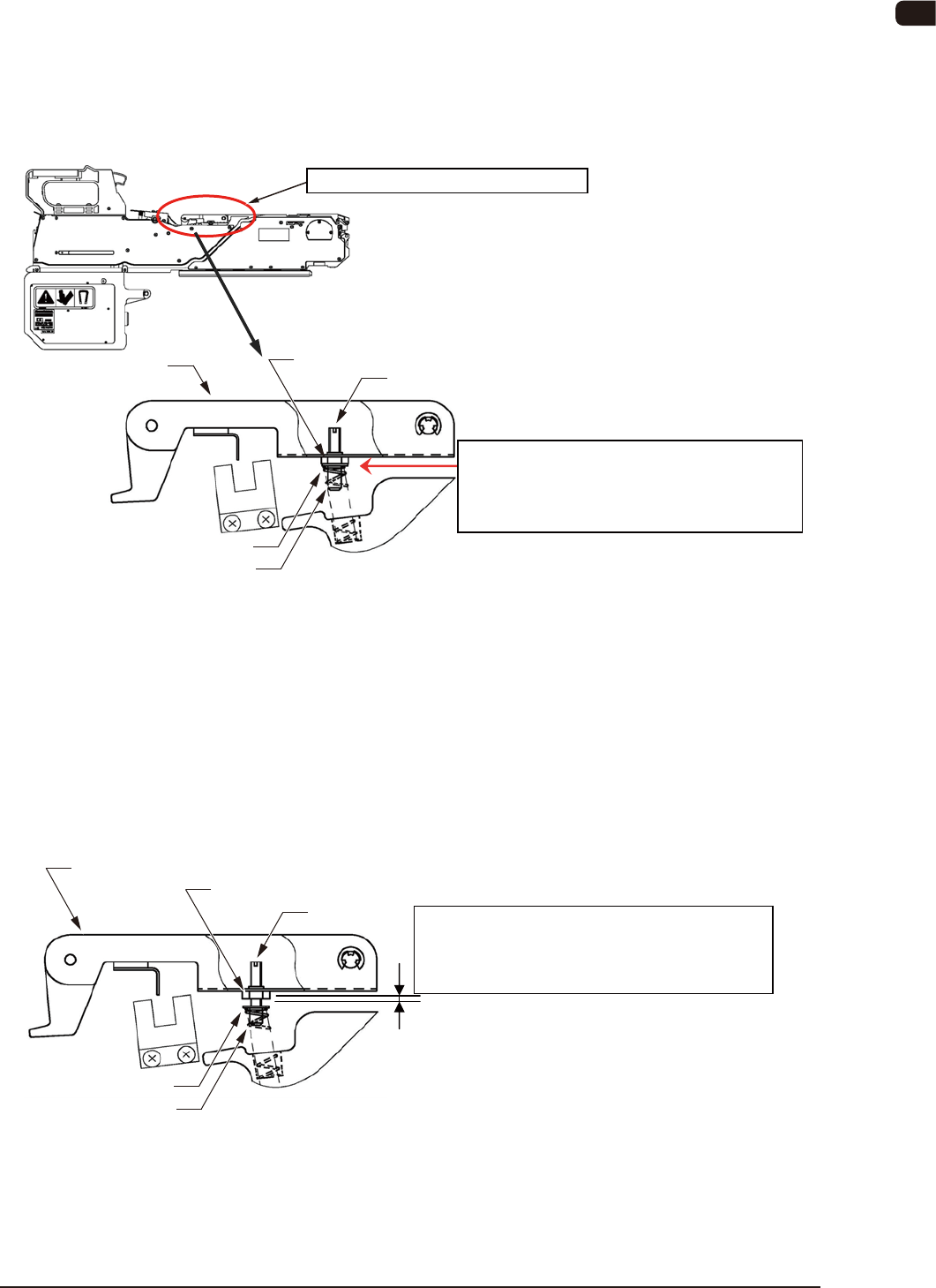
2.9 8 mm Cover Tape Tension Lever Section Spring Setup
•
Applicable Model : GT-28080 / 28081 / 28082 / 28083
•
Cover Tape Tension Lever Section Spring Standard Set Value
For the spring standard set values, the gap distance between the adjusting bolt
ange section and the hexagon nut should be "0 mm".
Tension Lever Section Spring Set Position
Standard Set Position:
Gap distance of "0 mm" between the flange
and hexagon nut
Cover Tape Tension Lever Section
Adjusting Bolt
Flange
Spring
Tension Lever
Hexagon Nut
Spring Standard Set Position FB48
•
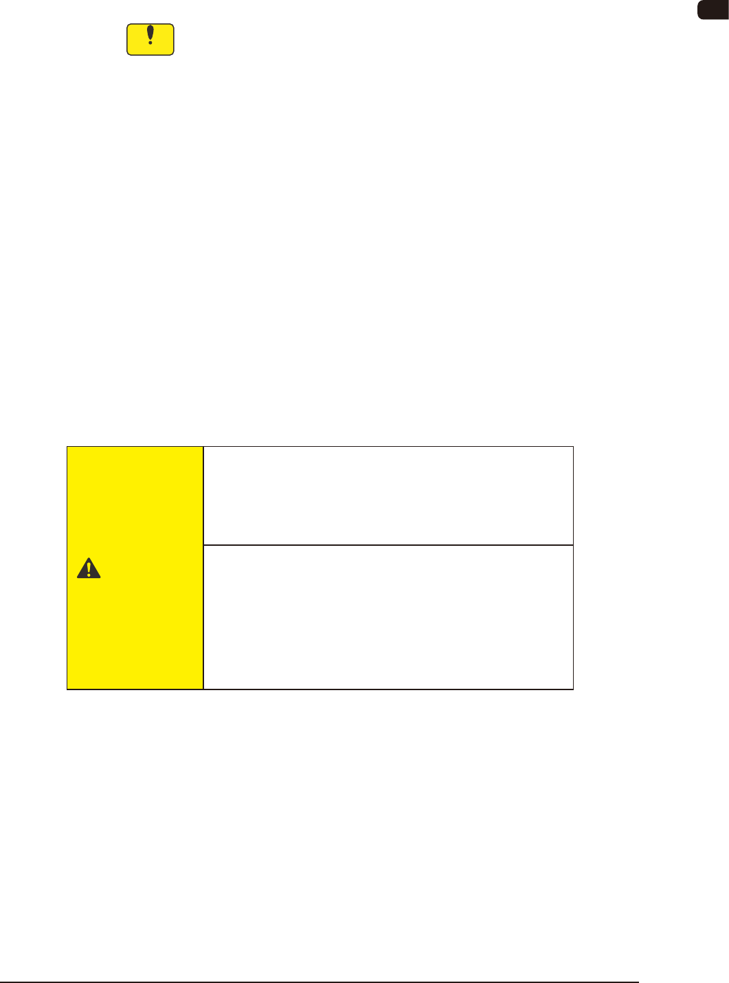
Setting when a cover tape take-up error (E1 Error) occurs frequently
during the tape feeder operation
Depending on the cover tape type, the tape might not be taken up normally and
might be caught in the suppressor releasing section gap, in the case that the
spring has been set to "standard".
When this error occurs frequently, change the tension lever spring setting as
shown in the following gure.
Tension Lever Section Spring Set Position
Changed Position:
Gap distance of "1.7 mm" between the flange
and hexagon nut
Adjusting Bolt
Flange
Spring
Tension Lever
Hexagon Nut
Spring Changed Position FB48-1

OM-1606
2-38
2. Attachment and Detachment of Tape
1009-002
•
Adjusting Procedure
Procedure
(1) Loosen the hexagon nut.
(2) Turn the groove on the adjusting bolt ve times clockwise using a
screwdriver.
(When the bolt is turned around ve times from the standard position, the
gap distance between the ange and hexagon nut becomes "1.7 mm" and the
tape take-up strength becomes 1.4 times more of the standard strength.
(3) Return the hexagon nut to the upper surface position and x.
OM-1606
3. Tape Feeder Attachment and Detachment Procedures
3-11005-002
3. Tape Feeder Attachment and Detachment
Procedures
Notice
Before setting the tape feeder onto the bank feeder change cart, follow
the instructions below.
•
Lock the caster brake (2 locations) of the bank feeder change cart.
•
If the tape feeder rises, it might cause breakdown to the pick-up nozzle
or machine (SIGMA-G4/G5) or pick-up error.
Set the tape feeder correctly.
•
After the suppressor has been moved up and down, for tape setting
or replacement, make sure that the tape feeder front hook is securely
caught, and that the suppressor does not rise.
With the dual tape feeder, make sure that the suppressor on the other
side does not rise either.
•
Make sure that the cover tape is not caught at the peeling section on
the suppressor.
•
Make sure that the excess tape section is appropriate (5 to 10 mm)
and that the tape end is not folded.
•
Make sure that the cover tape passes correctly onto the roller section
and that it has been inserted into the cover tape housing section.
Also, make sure that there is no sag in the cover tape.
CAUTION
•
When the bank feeder change cart is to be
moved, hold the handle and move it.
•
When setting the handle slider, take care that your
nger is not pressed down by the handle slider.
•
When the bank feeder change cart is to be
moved, take care that the cart does not hit your
foot.
•
When the bank feeder change cart is operated,
wear shoes protecting your toes or with a bottom
thickness of 10 mm or more.