OM-1606-006w_GT-28x.pdf - 第87页
OM-1606 4-9 4. Operation Panel 4.2.10 I/O Status Indication for Sensor , etc. This function uses seven-segment indicator as the status indicator for the sensor attached to the feeder. Procedure (1) Press the button and w…
OM-1606
4-8
4. Operation Panel
4.2.8 Continuous Feeding Operation
This operation repeats the minimum pitch feeding continuously.
Procedure
(1) Press the button to select the lane.
(Only for 8 mm width Tape Feeder)
(2) In the tensed cover tape condition (tension detection sensor ON), press the
button and keeping this condition, press the button.
While both the
button and button are being pressed at the same time,
the continuous feed is performed.
(3) Release your nger from either of the two buttons.
At that time, the minimum feed pitch operation is ended.
Note
In the case of slack cover tape, when the button is pressed (cover
tape tension detection sensor OFF), the cover tape take-up operation is
preceded.
4.2.9 Cancel the tape feed speed deceleration to return
When the tape feeding speed has been set to "Deceleration" in the component
library data, the dot indication
of the subject Fdr. No. ashes and the feed
pitch setup operation is disabled.
It is necessary to cancel the feed speed deceleration to return it to normal.
Procedure
(1) Press the button to select the lane.
(Only for 8 mm width Tape Feeder)
(2) Press the
button and within 2 seconds, press the button. Keep this
condition (two buttons are being pressed) for 2 seconds.
After the above operation for 2 seconds is conrmed, the dot display
is changed from ashing to lighting and the feed pitch setting operation is
enabled.
0907-001
OM-1606
4-9
4. Operation Panel
4.2.10 I/O Status Indication for Sensor, etc.
This function uses seven-segment indicator as the status indicator for the sensor
attached to the feeder.
Procedure
(1) Press the button and within 2 seconds, press the button and keep this
condition (two buttons are being pressed) for 2 seconds.
After the above operation for 2 seconds is conrmed, the mode transfers to
the I/O status indication mode.
Note
When this mode is to be ended, breaking the feeder power supply or
performing the mode transfer operation from this mode (above operation)
returns to the general display mode.
The items corresponding to each of the seven segments and I/O (Sensor and
Signal) are as follows.
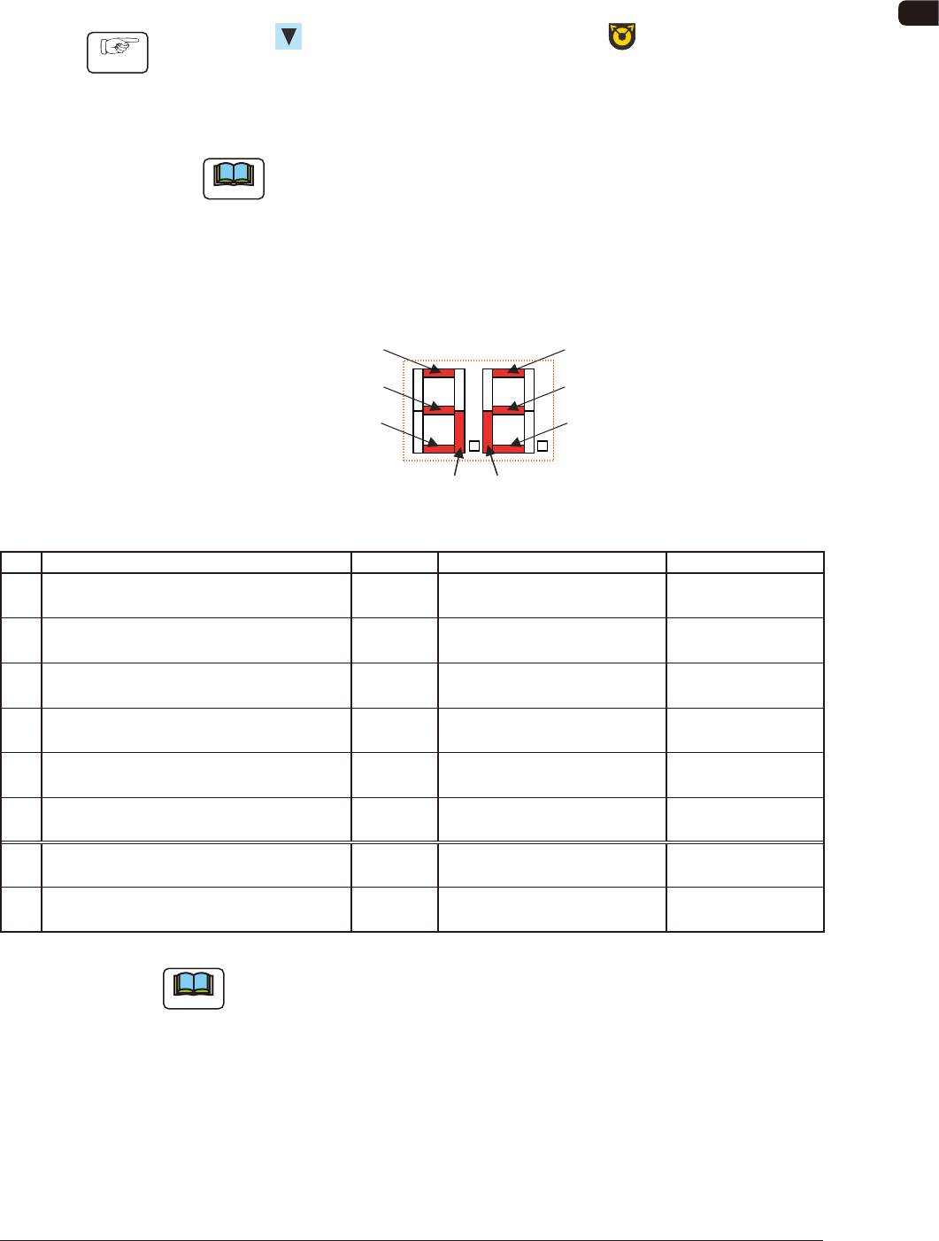
Seven Segments
[1]
[7] [8]
[2]
[3]
[4]
[5]
[6]
FD3
No. Sensor/Signal Name Lighting Status Remarks
1 Lane 1 Joint Detection Sensor ON (Low) E/R
(Light Emitted and Received)
Only for GD Type
2 Lane 1 Cover Tape Take-up Tension Detection
Sensor
ON (Low) E/NR
(Light Emitter and Not Received)
3 Lane 1 Sprocket Home Position Detection
Sensor
ON (Low) Magnetic Pole Detection Only for
GD-28081,28083 Type
4 Lane 2 Joint Detection Sensor ON (Low) E/R
(Light Emitted and Received)
Only for GD Type
5 Lane 2 Cover Tape Take-up Tension Detection
Sensor
ON (Low) E/NR
(Light Emitter and Not Received)
6 Lane 2 Sprocket Home Position Detection
Sensor
ON (Low) Magnetic Pole Detection Only for
GD-28081,28083 Type
7 Connection Conrmation Signal
(Output Signal to the Mounter Main Machine)
ON (Low)
8 READY Signal
(Output Signal to the Mounter Main Machine)
ON (Low)
TD1
Note
The layout of the seven segments in the display section is arranged as the order
of the sensor arrangement on the feeder.
0907-001

OM-1606
4-10
4. Operation Panel
Lane 2 Cover Tape Take-up
Tension Detection Sensor
Lane 1 Cover Tape Take-up
Tension Detection Sensor
Lane 2 Sprocket Home Position
Detection Sensor
Lane 1 Sprocket Home Position
Detection Sensor
Lane 2 Joint Detection Sensor
Lane 1 Joint Detection Sensor
Seven Segments
FD4
0907-001