OM-1606-006w_GT-28x.pdf - 第89页
OM-1606 4-1 1 4. Operation Panel 4.3 Error Codes and Splicing Guide If any error occurs during tape feeder operation, an error code is displayed on the digital display. Also, the guide for the splicing is displayed. • Er…

OM-1606
4-10
4. Operation Panel
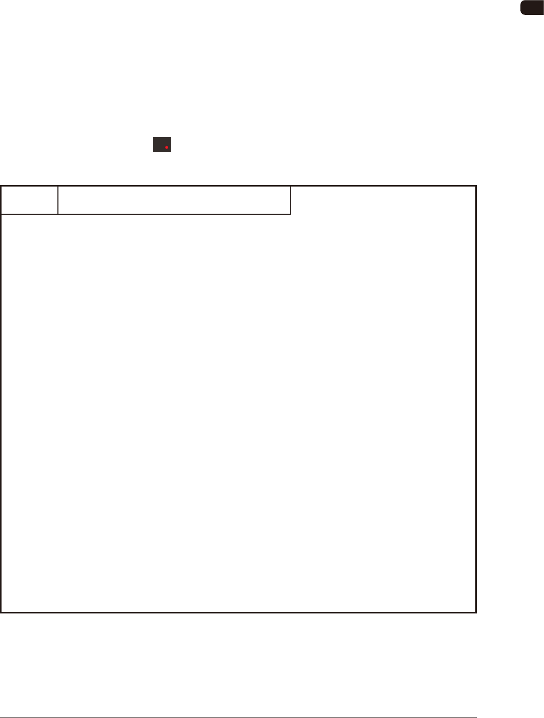
Lane 2 Cover Tape Take-up
Tension Detection Sensor
Lane 1 Cover Tape Take-up
Tension Detection Sensor
Lane 2 Sprocket Home Position
Detection Sensor
Lane 1 Sprocket Home Position
Detection Sensor
Lane 2 Joint Detection Sensor
Lane 1 Joint Detection Sensor
Seven Segments
FD4
0907-001
OM-1606
4-11
4. Operation Panel
4.3 Error Codes and Splicing Guide
If any error occurs during tape feeder operation, an error code is displayed on the
digital display.
Also, the guide for the splicing is displayed.
•
Error codes are divided into two classi cations: one is
feeder operation error
with prex of "E", and the other is
servo alarm system error
with prex of
"A".
•
Flashing
error code is indicated.
•
In the case of dual tape feeder, to guide to the lane where any errors occur, dot
indication
is
turned on
.
4.3.1 Feeder Operation Error Codes
[Detection Description] Even when the cover tape take-up motor is operating continuously
for 1 second, the cover tape tension detection sensor does not show
ON (E/NR) condition.
[Cause and Remedy]
•
Cover tape not set correctly.
⇒
Is the cover tape set correctly in the take-up gear ?
•
Cover tape has been damaged.
⇒
Set again and see the result.
•
Tape clogged at the cover tape housing section.
⇒
Is the cover tape housing section blocked with cover tape ?
(Open the cover and take it up)
•
The take-up gear does not rotate smoothly because of dirt or
something adhered.
⇒
Clean and maintain it to enable smooth rotation.
[Check Items]
•
Does the cover tape take-up motor smoothly rotate ?
⇒
Motor breakdown (disconnection, wear of the brush or commutator, or damage
to the shaft)
•
Does the cover tape tension detection sensor perform correctly ?
(Disconnection or breakdown)
•
Breakdown of control PCB.
(Breakdown of driving circuit step section)
E0 Cover Tape Take-up Error
0907-001
OM-1606
4-12
4. Operation Panel
[Detection Description] Even when the specied pitches of the tape feeding was being
performed, the cover tape tension detection sensor did not show
OFF (E/R) condition. (No sagging occurs).
[Cause and Remedy]
•
The cover tape is not correctly peeled and is taken up together
with the carrier tape.
⇒
When the tape was being set, it was set with the cover tape which has
not been completely peeled.
Set correctly and see the result.
•
Something (dirt) has adhered to the peeling section on the
suppressor, and it hinders the smooth feeding and peeling of the
cover tape.
⇒
Clean the suppressor and chute sections.
[Check Items]
•
Is the cover tape tension detection sensor operating correctly ?
⇒
Is there any debris in the slit on the peeling section of the suppressor ?
(Always E/NR condition)
E1 Cover Tape Roll-in Error
It is specially for the tape feeder (GD type) with the joint detection unit.
[Detection Description] Before the joint detection alarm is output from the machine
(SIGMA-G4/G5), the splicing section for supplemental components
is detected.
[Cause and Remedy]
•
The number of remaining components is not correctly controlled.
⇒
Is the total number of components correct before supplying the
supplemental components with splicing ?
E3 Joint Detection Error
1011-003