bnp-b2365(eng)b.pdf - 第111页
3. Setup 3 - 24 High-gain speci fications No. Abbrev. Parameter name Explanation Setting range (Unit) SV013 ILMT Current limit value Set the normal current (torque) limit value. (Limit values for both + and - direction.)…
3. Setup
3 - 23
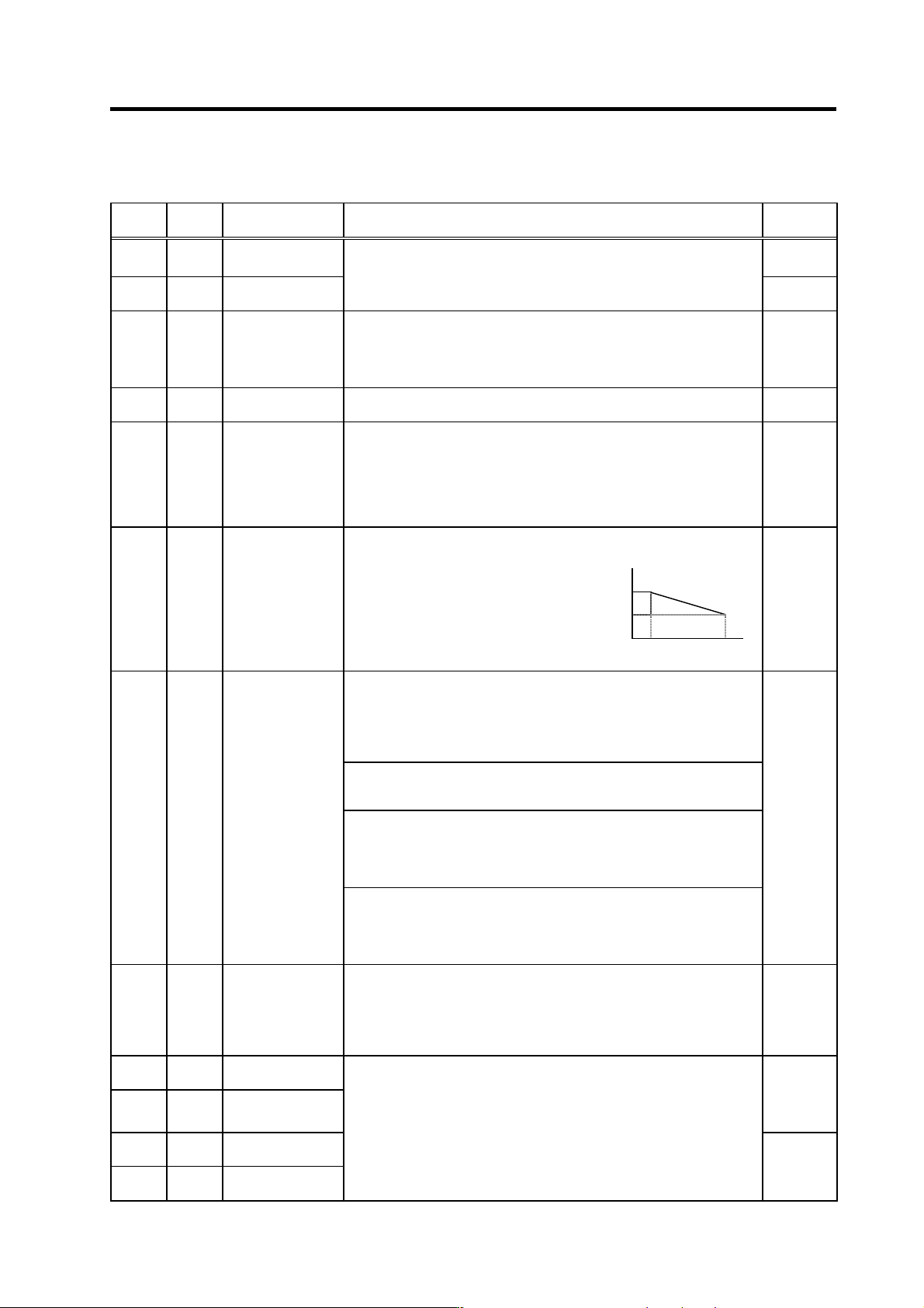
3-2-3 Servo parameter list
High-gain specifications
No. Abbrev. Parameter name Explanation
Setting
range (Unit)
SV001 PC1*
Motor side gear
ratio
1 to 32767
SV002 PC2*
Machine side gear
ratio
Set the motor side and machine side gear ratio.
For the rotary axis, set the total deceleration (acceleration) ratio.
Even if the gear ratio is within the setting range, the electronic gears may
overflow and cause an alarm.
1 to 32767
SV003 PGN1 Position loop gain 1
Set the position loop gain. The standard setting is "47".
The higher the setting value is, the more precisely the command can be
followed and the shorter the positioning time gets, however, note that a
bigger shock is applied to the machine during acceleration/deceleration.
When using the SHG control, also set SV004 (PGN2) and SV057 (SHGC).
1 to 200
(rad/s)
SV004 PGN2 Position loop gain 2
When using the SHG control, also set SV003 (PGN1) and SV057 (SHGC).
When not using the SHG control, set to "0".
0 to 999
(rad/s)
SV005 VGN1 Speed loop gain 1
Set the speed loop gain.
Set this according to the load inertia size.
The higher the setting value is, the more accurate the control will be,
however, vibration tends to occur.
If vibration occurs, adjust by lowering by 20 to 30%.
The value should be determined to be 70 to 80% of the value at the time
when the vibration stops.
1 to 999
VGN1
VGN2
VCS VLMT
SV006 VGN2 Speed loop gain 2
If the noise is bothersome at high speed
during rapid traverse, etc, lower the speed
loop gain.
As in the right figure, set the speed loop
gain of the speed 1.2 times as fast as the
motor’s rated speed, and use this with
SV029 (VCS).
When not using, set to "0".
0
(Rated speed*1.2)
-1000 to
1000
Set this when the limit cycle occurs in the full-closed loop, or overshooting
occurs in positioning.
Select the control method with SV027 (SSF1)/bit1, 0 (vcnt).
Normally, use "Changeover type 2".
When you set this parameter, make sure to set the torque offset (SV032
(TOF)). When not using, set to "0".
No changeover
When SV027 (SSF1)/bit1, 0 (vcnt)=00
The delay compensation control is always valid.
Changeover type 1
When SV027 (SSF1)/bit1, 0 (vcnt)=01
The delay compensation control works when the command from the NC
is "0".
Overshooting that occurs during pulse feeding can be suppressed.
SV007 VIL
Speed loop delay
compensation
Changeover type 2
When SV027 (SSF1)/bit1, 0 (vcnt)=10
The delay compensation control works when the command from the NC
is "0" and the position droop is "0". Overshooting or the limit cycle that
occurs during pulse feeding or positioning can be suppressed.
0 to 32767
SV008 VIA
Speed loop lead
compensation
Set the gain of the speed loop integration control.
The standard setting is "1364". During the SHG control, the standard
setting is "1900". Adjust the value by increasing/decreasing it by about 100
at a time.
Raise this value to improve contour tracking precision in high-speed
cutting. Lower this value when the position droop vibrates (10 to 20Hz).
1 to 9999
SV009 IQA
Current loop q axis
lead compensation
SV010 IDA
Current loop d axis
lead compensation
Set the gain of current loop.
As this setting is determined by the motor’s electrical characteristics, the
setting is fixed for each type of motor.
Set the standard values for all the parameters depending on each motor
type.
1 to 20480
SV011 IQG
Current loop q axis
gain
SV012 IDG
Current loop d axis
gain
1 to 8192
Parameters with an asterisk * in the abbreviation, such as PC1*, are validated with the NC power turned ON again.
3. Setup
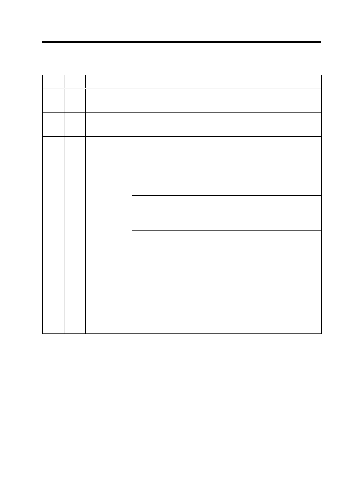
3 - 24
High-gain specifications
No. Abbrev. Parameter name Explanation
Setting
range (Unit)
SV013 ILMT Current limit value
Set the normal current (torque) limit value. (Limit values for both + and -
direction.)
When the value is "500" (a standard setting), the maximum torque is
determined by the specification of the motor.
0 to 999
(Stall
[rated]
current %)
SV014 ILMTsp
Current limit value in
special control
Set the current (torque) limit value in a special control (initial absolute
position setting, stopper control, etc). (Limit values for both of the + and -
directions.)
Set to "500" when not using.
0 to 999
(Stall
[rated]
current %)
SV015 FFC
Acceleration rate
feed forward gain
When a relative error in the synchronous control is large, apply this
parameter to the axis that is delaying. The standard setting value is "0".
For the SHG control, set to "100".
To adjust a relative error in acceleration/deceleration, increase the value by
50 to 100 at a time.
0 to 999
(%)
Set this when the protrusion (that occurs due to the non-sensitive band by
friction, torsion, backlash, etc.) at quadrant change is too large.
This compensates the torque at quadrant change.
This is valid only when the lost motion compensation (SV027 (SSF1.lmc))
is selected.
Type 1: When SV027 (SSF1)/bit9, 8 (lmc)=01
Set the compensation amount based on the motor torque before the
quadrant change.
The standard setting is "100". Setting to "0" means the compensation
amount is zero.
Normally, use Type 2.
-1 to 200
(%)
Type 2: When SV027 (SSF1)/bit9, 8 (lmc)=10
Set the compensation amount based on the stall (rated) current of the
motor.
The standard setting is double of the friction torque. Setting to "0"
means the compensation amount is zero.
-1 to 200
(Stall
[rated]
current %)
Type3 When SV082(SSF5)/bit1(lmc3)=1
Set the compensation amount based on the stall current of the motor.
Setting on SV082/bit1(lmc3) has a priority over SV027/bit9,8(lmc)
-1 to 200
(Stall
current %)
SV016 LMC1
Lost motion
compensation 1
When you wish different compensation amount depending on the direction
When SV041 (LMC2) is "0", compensate with the value of SV016
(LMC1) in both of the + and -directions.
If you wish to change the compensation amount depending on the
command direction, set this and SV041 (LMC2). (SV016: + direction,
SV041: - direction. However, the directions may be opposite depending
on other settings.)
When "-1" is set, the compensation won’t be performed in the direction of
the command.
Parameters with an asterisk * in the abbreviation, such as PC1*, are validated with the NC power turned ON again.
3. Setup
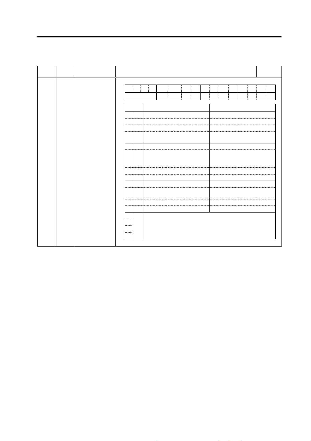
3 - 25
High-gain specifications
No. Abbrev. Parameter name Explanation
Setting
range (Unit)
HEX setting
FEDCB A 98765 4 3 2 10
spm mpt mp abs vdir fdir vfb seqh dfbx fdir2
bit Meaning when "0" is set Meaning when "1" is set
0 fdir2 Speed feedback forward polarity Speed feedback reverse polarity
1 dfbx Dual feedback control stop Dual feedback control start
2 seqh
3vfb
Speed feedback filter stop Speed feedback filter stop
(2250Hz)
4 fdir Position feedback forward polarity Position feedback reverse polarity
5vdir
Standard setting HA motor (4 pole motor)
Detector installation position 90
degrees (B, D)
6
SV017 SPEC*
Servo specification
selection
7 abs Incremental control Absolute position control
8 mp MP scale 360P (2mm pitch) MP scale 720P (1mm pitch)
9
mpt
MP scale ABS detection NC
control
MP scale ABS detection
automatic (Standard setting)
A
B
C
D
E
spm
F
0 : Setting for normal use
1 : When using the S type drive unit (Only in the case of MDS-C1-Vx)
2 to F : Setting probhited
(Note) Set to "0" for bits with no particular description.
Parameters with an asterisk * in the abbreviation, such as PC1*, are validated with the NC power turned ON again.