bnp-b2365(eng)b.pdf - 第125页
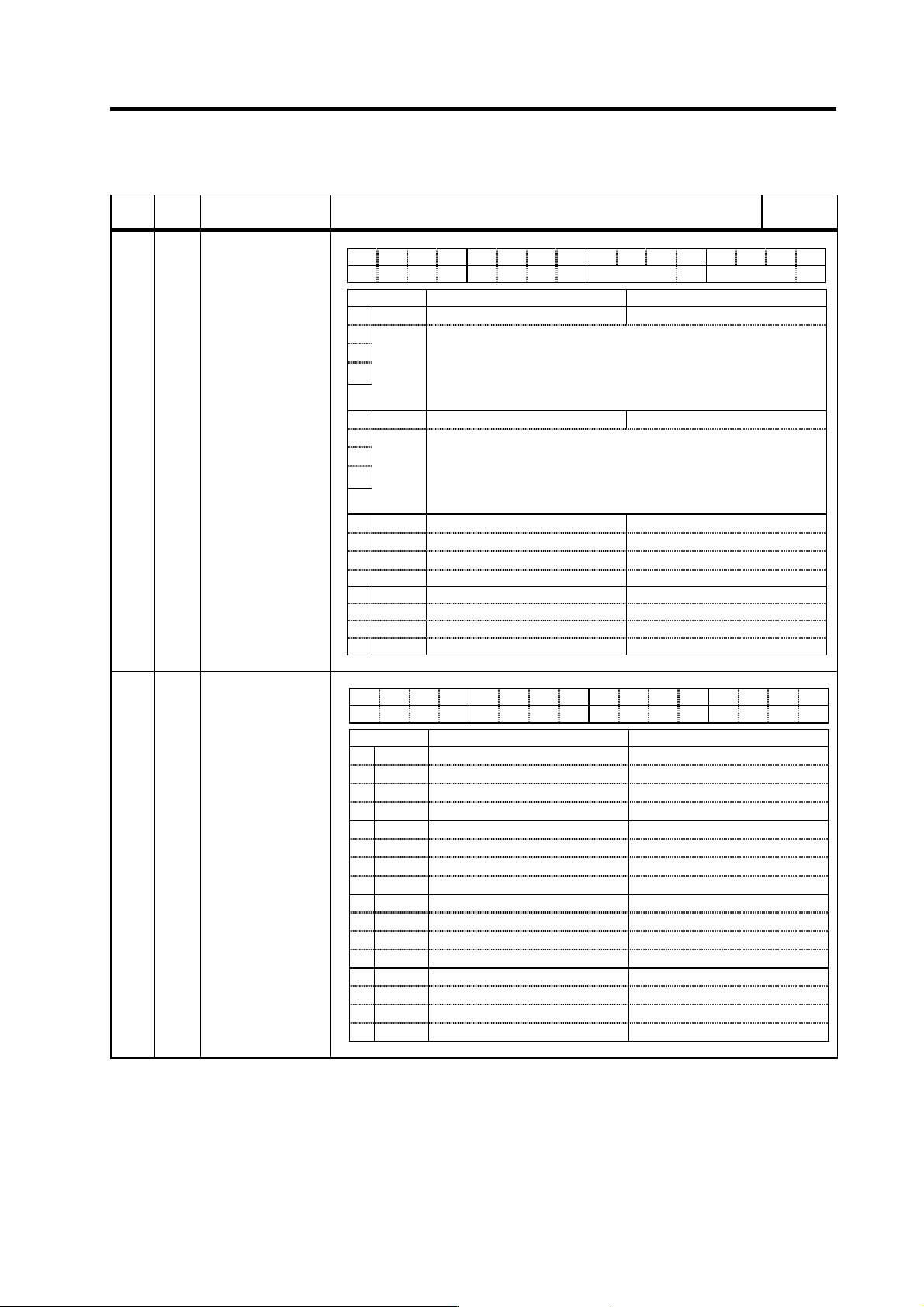
3. Setup 3 - 38 High-gain speci fications No. Abbrev. Parameter name Explanation Setting range (Unit) SV085 LMCk Lost motion compensation spring constant Set the machine system's spring constant when using lost moti…
3. Setup
3 - 37
High-gain specifications
No.
Abbrev.
Parameter name Explanation
Setting
range (Unit)
F EDCBA98765 4 3 2 10
nfd5 nfd4
bit Meaning when set to 0 Meaning when set to 1
0
1 Set the filter depth for Notch filter 4 (SV038).
2
Setting value Deep ← → Shallow
3 000 001 010 011 100 101 110 111
nfd4
Depth (dB)
-
∞
-18.1 -12.0 -8.5 -6.0 -4.1
-2.5 -1.2
4
5 nfd5 Set the filter depth for Notch filter 5 (SV046).
6
Setting value Deep ← → Shallow
7
000 001 010 011 100 101 110 111
Depth (dB) -∞ -18.1 -12.0 -8.5 -6.0 -4.1
-2.5 -1.2
8
9
A
B
C
D
E
F
SV083 SSF6
Servo function
selection 6
(Note) Set to "0" for bits with no particular description.
F E D C B A 9 8 7 6 5 4 3 2 1 0
bit Meaning when set to 0 Meaning when set to 1
0
1
2
3
4
5
6
7
8
9
A
B
C
D
E
F
SV084 SSF7
Servo function
selection 7
(Note) Set to "0" for bits with no particular description.

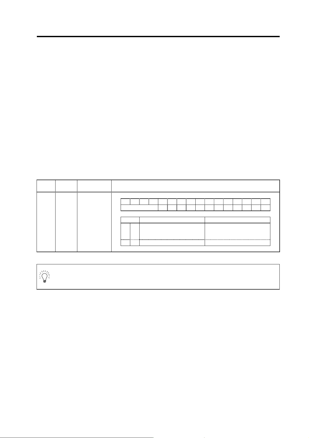
3. Setup
3 - 38
High-gain specifications
No.
Abbrev.
Parameter name Explanation
Setting
range (Unit)
SV085 LMCk
Lost motion
compensation
spring constant
Set the machine system's spring constant when using lost motion
compensation type 3.
0 to 32767
SV086 LMCc
Lost motion
compensation
viscous coefficient
Set the machine system's viscous coefficient when using lost motion
compensation type 3.
0 to 32767
SV087 FHz4
Notch filter
frequency 4
0 to 2250
(Hz)
SV088 FHz5
Notch filter
frequency 5
Set the vibration frequency to suppress if machine vibration occurs. (Valid at
141 or more) When not using, set to "0".
To use this function, set to not "0" (normally "1") when turning the power ON.
This function cannot be used with adaptive filter.
0 to 2250
(Hz)
SV089
:
SV100
Not used. Set to "0".
0
3. Setup
3 - 39
3-3 Setting the initial parameters for the servo drive unit
(Standard specifications)
The servo parameters must be set before the servo system can be started up. The servo parameters
are input from the NC. The input method differs according to the NC being used, so refer to each NC
Instruction Manual.
3-3-1 Setting the standard parameters
When starting up the system, first set the standard parameters listed in "3-3-2 List of standard
parameters for each servomotor". For the parameters shown below, check the machine and servo
system specifications and determine the setting value.
(1) Basic specification pa rameters
[1] When performing absolute position control, set SV017/bit7=1. This may be automatically set by
NC system parameter setting, depending on NC model. (Setting on the servo parameter screen
is not valid.)
[2] For HA053N, HA13N, HA23N, HA33N motors, if the connector direction of the motor end
detector with motor power supply connector is 90°, se t SV017/bit5=1. If the angl e is 180°, use a
standard setting (SV017/bit5=0).
Setting basic specification parameters
Standard specifications
No. Abbrev.
Parameter
name
Explanation
F E D C B A 9 8 7 6 5 4 3 2 1 0
spm mpt mp abs vdir fdir vfb seqh dfbx
bit Meaning when set to 0 Meaning when set to 1
5 vdir
Standard setting
HA motor (4 pole motor)
Detector installation position 90
degrees (B, D)
7 abs Incremental control Absolute position control
SV017 SPEC*
Servo
specification
selection 1
POINT
Setting of absolute position control (SV017/bit7) may be set automatically by NC
system parameter setting, dependi ng on NC model. In this case, setting on the serv o
parameter screen is not valid.