bnp-b2365(eng)b.pdf - 第129页
3. Setup 3 - 42 Setting for full-closed loop co ntrol Standard specifications No. Abbrev. Parameter name Explanation F E D C B A 98765 4 3 2 10 mpt mp abs vdir fdir s pw v seqh dfbx bit Meaning when set to 0 Meaning when…
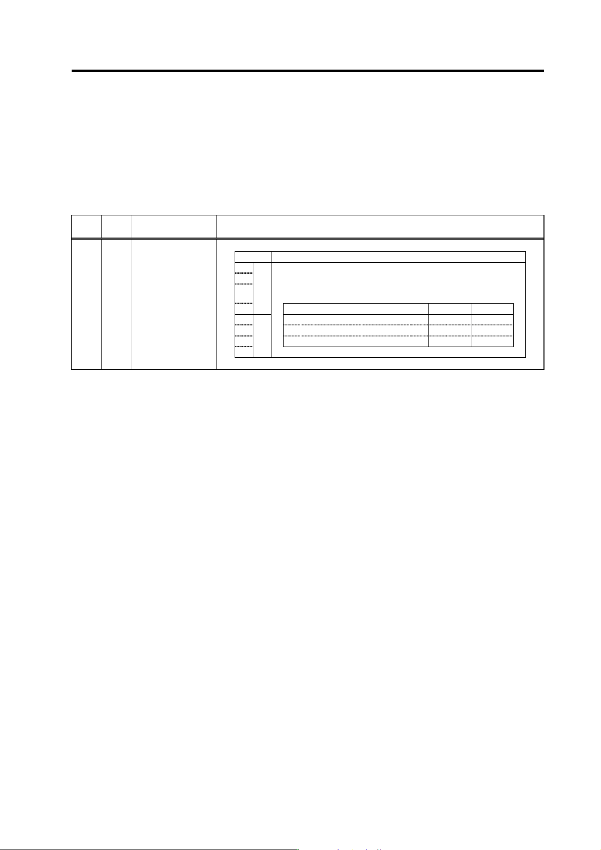
3. Setup
3 - 41
(3) Detector related parameters
(a) For semi-closed loop control
For control using only the motor end detector, specify the settings shown in the table below. For
speed and current synchro nous control, refer to sectio n "2-4-3 Connecting the synchron ous control
system".
Setting for semi-closed loop control
Standard specifications
No.
Abbr
ev.
Parameter name
Explanation
bit Details
8
9
A
ent
Set the detector type.
Set the position detector type for “pen”, and the speed detector type
for “ent”. In the case of the semi-closed loop control, set the same
value for “pen” and “ent”.
B
Detector model pen setting ent setting
C OSE104 0 0
D OSA104 1 1
E
pen
OSE105, OSA105 2 2
F
SV025 MTYP*
Motor/Detector type
Parameters with an asterisk * in the abbreviation, such as PC1*, are validated with the NC power turned ON again.
(b) For full-closed loop control
Some parameter settings must be specified in order to use the machine end detector. These
settings are determined by type or the installation conditions of the linear scale and the ball screw
end detector.
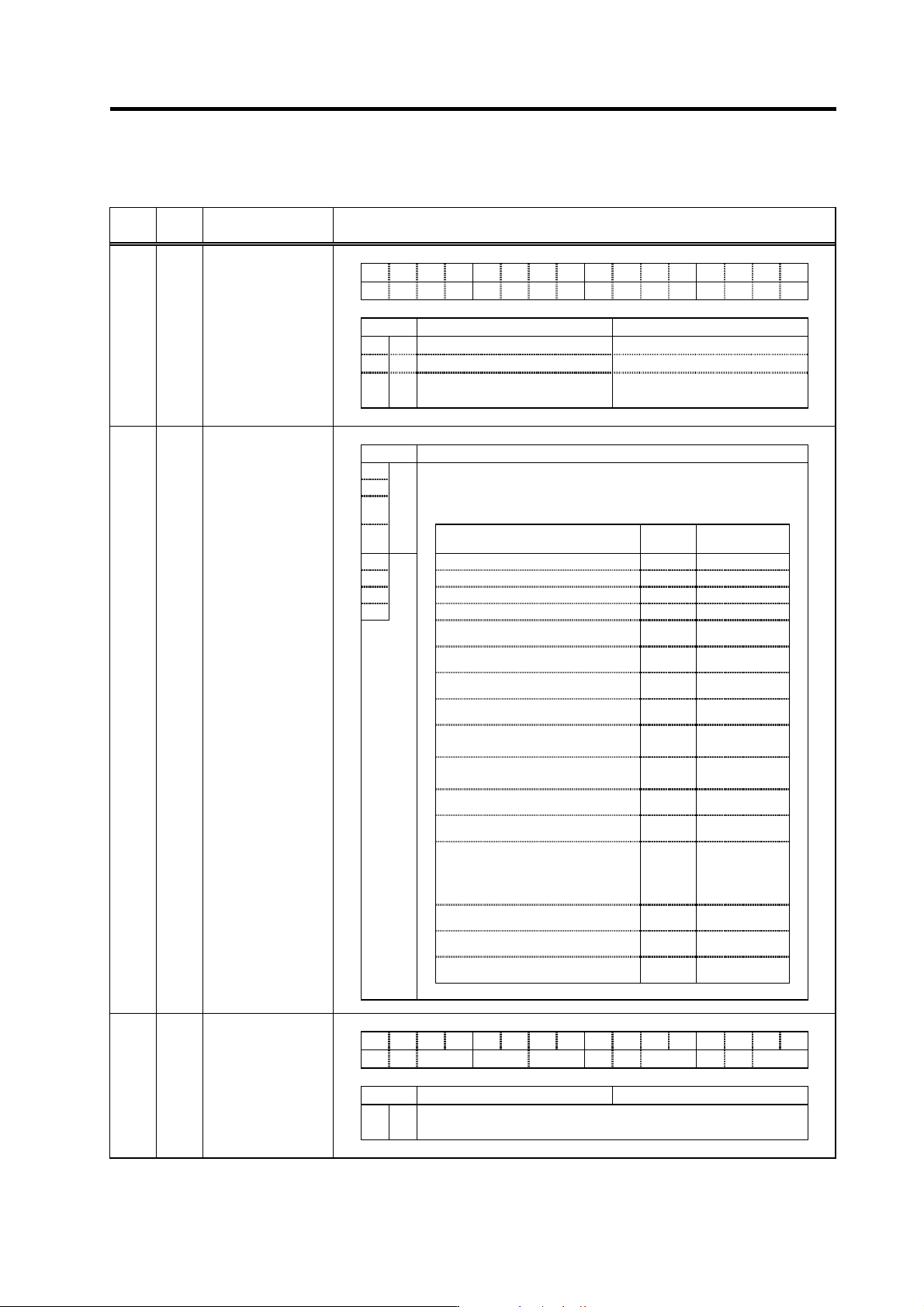
[1] The SV025/bit8 to B (ent) setting must be specified according to the motor end detector
specifications, in the same manner as for semi-closed loop control. For current synchronous
control, however, refer to section "2-4-3 Connecting the synchronous control system".
[2] If the polarities of the motor end detector and the machine end detector do not match, specify
SV017/bit4=1 setting.
[3] To use AT342, specify SV027/bit6=1 setting.
[4] To use the MP scale, specify SV017/bit8 setting in accordance with the scale specifications.
For absolute position control, spe cify SV017/bit9=1 setting.
[5] For ABZ phase pulse output type relative position detection scale with constant Z-phase
detection position without regard to the travel direction, specify SV027/bit6=1 setting. Z-phase
detection occurs as follows: Plus-direction travel: Rising edge detection, Minus-direction
travel: Falling edge detection
[6] For machine end absolute position control at the rotation axis, specify SV081/bit1=1 setting.
[7] For speed and current synchronous control, refer to "2-4-3 Connecting the synchronous
control system".
3. Setup
3 - 42
Setting for full-closed loop control
Standard specifications
No.
Abbrev.
Parameter name
Explanation
F EDCBA98765 4 3 2 10
mpt mp abs vdir fdir
s
pw
v
seqh dfbx
bit Meaning when set to 0 Meaning when set to 1
4 fdir Position feedback forward polarity Position feedback reverse polarity
8 mp MP scale 360P (2mm pitch) MP scale 720P (1mm pitch)
9 mpt
MP scale ABS detection NC
control
MP scale ABS detection
automatic (Standard swetting)
SV017 SPEC*
Servo specification
selection
bit Explanation
8
9
A
ent
Set the detector type.
Set the position detector type for “pen”, and the speed detector type
for “ent”. In the case of the semi-closed loop control, set the same
value for “pen” and “ent”.
B
Detector model name
pen
setting
ent setting
C OSE104 0 (Note) 0
D OSA104 1 (Note) 1
E
pen
OSE105, OSA105 2 (Note) 2
F 3 (Note) 3
OHE25K-ET,OSE104-ET 4
Setting
impossible
OHA25K-ET,OSA104-ET 5
Setting
impossible
OSE105-ET,OSA105-ET 6
Setting
impossible
7
Setting
impossible
Relative position detection scale,
MP type (Mitsubishi Heavy Industries)
8
Setting
impossible
AT41 (Mitsutoyo), FME type,
FLE type (Futaba)
9
Setting
impossible
AT342 (Mitsutoyo) A
Setting
impossible
B
Setting
impossible
The setting of the slave axis in th
e
speed/current synchroniza tion control.
When the master axis is the semi-closed
control.
C
C
(Current
synchronization)
D
Setting
impossible
E
Setting
impossible
F
Setting
impossible
(Note) Setting for semi-closed loop control
SV025 MTYP*
Motor/Detector type
F EDCBA98765 4 3 2 10
aflt zrn2 afse ovs lmc zrn3 vfct upc vcnt
bit Meaning when set to 0 Meaning when set to 1
6 zrn3
ABZ scale: Set to "1" to fix Z-phase detection edge.
Absolute position scale: Set to "1" in using AT342.
SV027 SSF1
Servo function
selection 2
Parameters with an asterisk * in the abbreviation, such as PC1*, are validated with the NC power turned ON again.
3. Setup
3 - 43
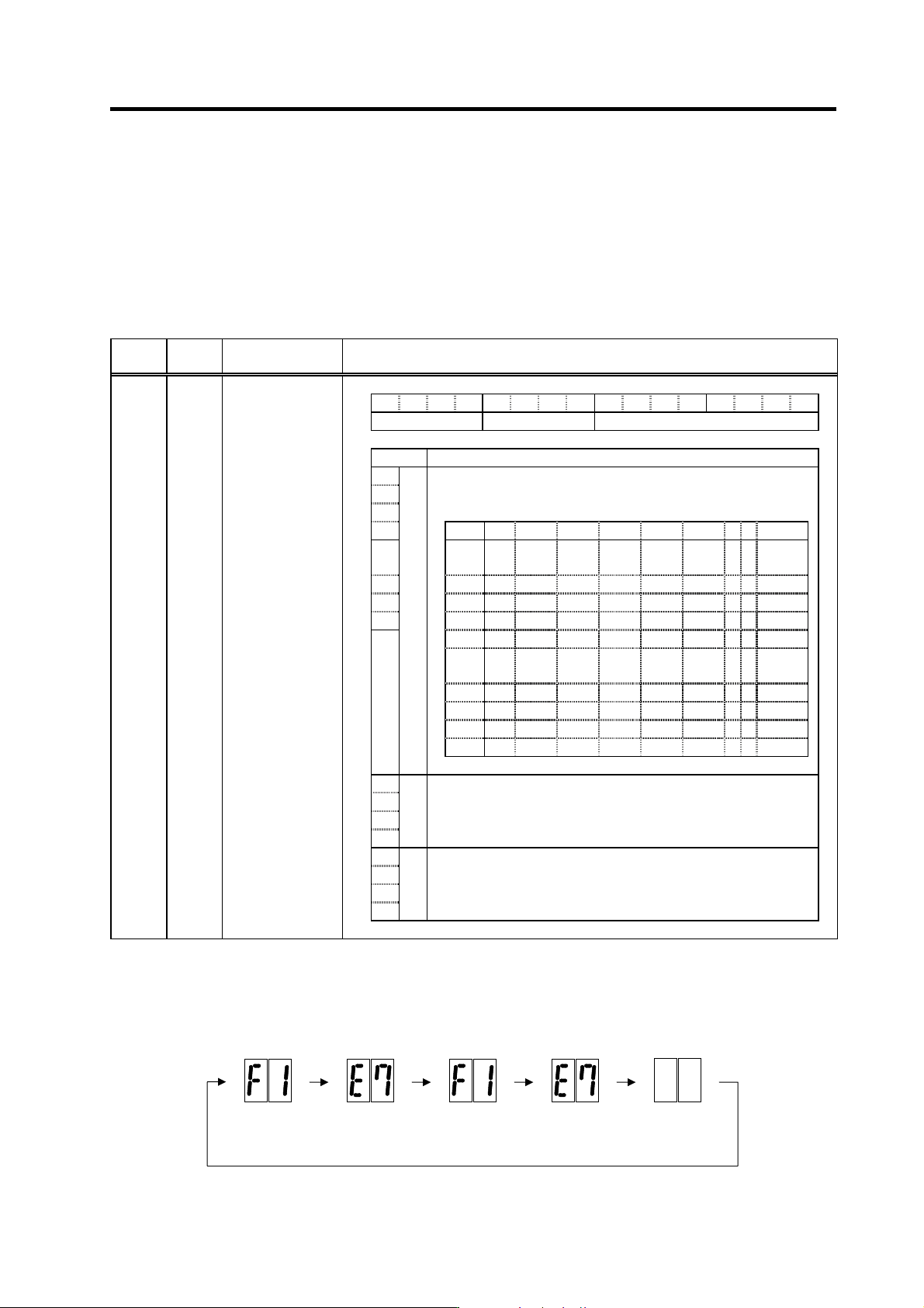
(4) Setting the power supply type
Set the drive unit connected to the power supply unit with the CN4 connector. This does not need
to be set if the power supply for the axis is not connected with the CN4 connector. (Set "0000".)
If the power supply unit is connected with the spindle drive unit, the parameters do not need to be
set on the servo side. When connected to a 2-axis servo drive unit (MDS-C1-V2), set the power
supply type for one of the two target axes.
Setting power supply type
Standard specifications
No. Abbrev. Parameter name Explanation
F E D C B A 9 8 7 6 5 4 3 2 1 0
amp rtyp ptyp
bit Explanation
0
1
When the CN4 connector of the drive unit and the power supply are
connected, setting below is necessary.
2 To validate the external emergency stop function, add 40h.
3 Setting 0x 1x 2x 3x 4x 5x 6x 7x 8x
4
ptyp
x0
Not
used
CV-300
5 x1 CV-110 CR-10
6 x2 CV-220 CR-15
7 x3 CR-22
x4
C
V-3
7
CR-37
x5 CV-150
MDS-B-
CVE-450
MDS-B-
CVE-550
x6
C
V-5
5
CV-260 CR-55
x7 CV-370
x8
C
V-7
5
CR-75
x9 CV-185 CR-90
8 Set the regenerative resistor type when MDS-A-CR is used.
9 Set "0" when using MDS-C1-CV (power supply regeneration).
A
B
rtyp
C Always set "0".
D
E
amp
F
SV036 PTYP*
Power supply type
Parameters with an asterisk * in the abbreviation, such as PC1*, are validated with the NC power turned ON again.
If alarm 7F occurs after setting the initial parameters, turn the drive unit power ON again. If the unit's
LEDs indicate the following emergency stop state, the unit has started up normally.
Normal LED display when NC power is turned ON (1st axis)
F1
F+axis No.
E7
Emergency
sto
p
Not lit
F1
F+axis No.
E7
Emergency
sto
p