bnp-b2365(eng)b.pdf - 第138页
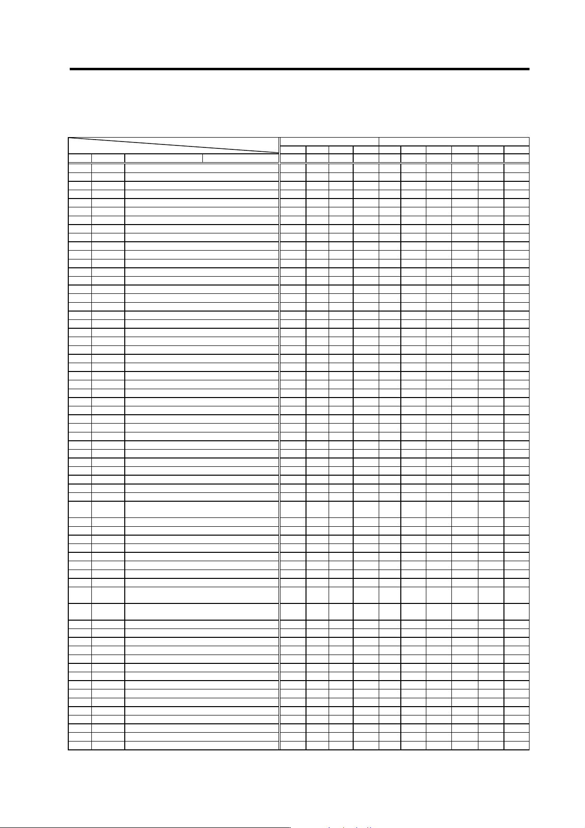
3. Setup 3 - 51 3-3-3 Servo parameter list Standard specifications No. Abbrev. Parameter name Explanation Setting range (Unit) SV001 PC1* Motor side gear ratio 1 to 32767 SV002 PC2* Machine side gear ratio Set the motor …
3. Setup
3 - 50
(7) HA series (Small capacity, Low-inertia 3000 r/min rating)
Standard specifications
Small capacity HA motor Low-inertia HA motor 3000 r/min rating Motor
Parameter
HA053A HA13N HA23N HA33N HA53L HA103L HA153L HA203L HA303L HA503L
No. Abbrev. Details Unit capacity 01 01 03 03 10 20 20 35 45 70
SV001 PC1 Motor side gear ratio --- --- --- --- --- --- --- --- --- ---
SV002 PC2 Machine side gear ratio --- --- --- --- --- --- --- --- --- ---
SV003 PGN1 Position loop gain 1 33 33 33 33 33 33 33 33 33 33
SV004 PGN2 Position loop gain 2 0 0 0 0 0 0 0 0 0 0
SV005 VGN1 Speed loop gain 1 70 70 100 100 30 30 30 30 30 50
SV006 VGN2 Speed loop gain 2 0 0 0 0 0 0 0 0 0 0
SV007 VIL Speed loop delay compensation 0 0 0 0 0 0 0 0 0 0
SV008 VIA Speed loop lead compensation 1364 1364 1364 1364 1364 1364 1364 1364 1364 1364
SV009 IQA Current loop q axis lead compensation 2048 2048 2048 2048 2048 2048 2048 2048 2048 2048
SV010 IDA Current loop d axis lead compensation 2048 2048 2048 2048 2048 2048 2048 2048 2048 2048
SV011 IQG Current loop q axis gain 256 256 224 224 512 512 512 512 256 256
SV012 IDG Current loop d axis gain 256 256 224 224 512 512 512 512 512 512
SV013 ILMT Current limit value 500 500 500 500 500 500 500 500 500 500
SV014 ILMTsp Current limit value in special control 500 500 500 500 500 500 500 500 500 500
SV015 FFC Acceleration rate feed forward gain 0 0 0 0 0 0 0 0 0 0
SV016 LMC1 Lost motion compensation 1 0 0 0 0 0 0 0 0 0 0
SV017 SPEC Servo specifications selection 1 0000 0000 0000 0000 0000 0000 0000 0000 0000 0000
SV018 PIT Ball screw pitch --- --- --- --- --- --- --- --- --- ---
SV019 RNG1 Position detector resolution --- --- --- --- --- --- --- --- --- ---
SV020 RNG2 Speed detector resolution --- --- --- --- --- --- --- --- --- ---
SV021 OLT Overload detection time constant 60 60 60 60 60 60 60 60 60 60
SV022 OLL Overload detection level 150 150 150 150 150 150 150 150 150 150
SV023 OD1 Excessive error detection width during servo ON 6 6 6 6 6 6 6 6 6 6
SV024 INP In-position detection width 50 50 50 50 50 50 50 50 50 50
SV025 MTYP Motor/detector type xx8C xx8D xx8E xx8F xx30 xx31 xx3A xx32 xx33 xx34
SV026 OD2 Excessive error detection width during servo OFF 6 6 6 6 6 6 6 6 6 6
SV027 SSF1 Servo function selection 1 4000 4000 4000 4000 4000 4000 4000 4000 4000 4000
SV028 0 0 0 0 0 0 0 0 0 0
SV029 VCS Speed at the change of speed loop gain 0 0 0 0 0 0 0 0 0 0
SV030 IVC Voltage dead time compensation / current bias 1 0 0 0 0 0 0 0 0 0 0
SV031 OVS1 Overshooting compensation 1 0 0 0 0 0 0 0 0 0 0
SV032 TOF Torque offset 0 0 0 0 0 0 0 0 0 0
SV033 SSF2 Servo function selection 2 0000 0000 0000 0000 0000 0000 0000 0000 0000 0000
SV034 SSF3 Servo function selection 3 0000 0000 0000 0000 0000 0000 0000 0000 0000 0000
SV035 SSF4 Servo function selection 4 0000 0000 0000 0000 0000 0000 0000 0000 0000 0000
SV036 PTYP Power supply type 0000 0000 0000 0000 0000 0000 0000 0000 0000 0000
SV037 JL Load inertia scale 0 0 0 0 0 0 0 0 0 0
SV038 FHz1 Notch filter frequency 1 0 0 0 0 0 0 0 0 0 0
SV039 LMCD Lost motion compensation timing 0 0 0 0 0 0 0 0 0 0
SV040 LMCT
Lost motion compensation non-sensitive band
/current bias 2
0 0 0 0 0 0 0 0 0 0
SV041 LMC2 Lost motion compensation 2 0 0 0 0 0 0 0 0 0 0
SV042 OVS2 Overshooting compensation 2 0 0 0 0 0 0 0 0 0 0
SV043 OBS1 Disturbance observer filter frequency 0 0 0 0 0 0 0 0 0 0
SV044 OBS2 Disturbance observer gain 0 0 0 0 0 0 0 0 0 0
SV045 TRUB Frictional torque/current bias 3 0 0 0 0 0 0 0 0 0 0
SV046 0 0 0 0 0 0 0 0 0 0
SV047 EC Inductive voltage compensation gain 100 100 100 100 100 100 100 100 100 100
SV048 EMGrt Vertical axis drop prevention time 0 0 0 0 0 0 0 0 0 0
SV049 PGN1sp
Position loop gain 1 in spindle synchronous
control
15 15 15 15 15 15 15 15 15 15
SV050 PGN2sp
Position loop gain 2 in spindle synchronous
control
0 0 0 0 0 0 0 0 0 0
SV051 DFBT Dual feedback control time constant 0 0 0 0 0 0 0 0 0 0
SV052 DFBN Dual feedback control non-sensitive band 0 0 0 0 0 0 0 0 0 0
SV053 OD3 Excessive error detection width in special control 0 0 0 0 0 0 0 0 0 0
SV054 IRE Overrun detection width in closed loop control 0 0 0 0 0 0 0 0 0 0
SV055 EMGx Max. gate off delay time after emergency stop 0 0 0 0 0 0 0 0 0 0
SV056 EMGt Deceleration time constant at emergency stop 0 0 0 0 0 0 0 0 0 0
SV057 SHGC SHG control gain 0 0 0 0 0 0 0 0 0 0
SV058 SHGCsp SHG control gain in spindle synchronous control 0 0 0 0 0 0 0 0 0 0
SV059 TCNV Collision detection torque estimating gain 0 0 0 0 0 0 0 0 0 0
SV060 TLMT Collision detection level 0 0 0 0 0 0 0 0 0 0
SV061 DA1NO D/A output channel 1 data No. 0 0 0 0 0 0 0 0 0 0
SV062 DA2NO D/A output channel 2 data No. 0 0 0 0 0 0 0 0 0 0
SV063 DA1MPY D/A output channel 1 output scale 0 0 0 0 0 0 0 0 0 0
SV064 DA2MPY D/A output channel 2 output scale 0 0 0 0 0 0 0 0 0 0
SV065 0 0 0 0 0 0 0 0 0 0
3. Setup
3 - 51
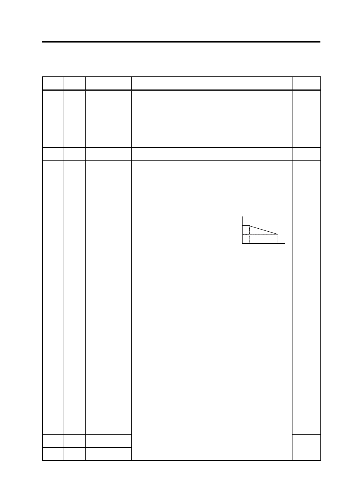
3-3-3 Servo parameter list
Standard specifications
No. Abbrev. Parameter name Explanation
Setting
range (Unit)
SV001 PC1*
Motor side gear
ratio
1 to 32767
SV002 PC2*
Machine side gear
ratio
Set the motor side and machine side gear ratio.
For the rotary axis, set the total deceleration (acceleration) ratio.
Even if the gear ratio is within the setting range, the electronic gears may
overflow and cause an alarm.
1 to 32767
SV003 PGN1 Position loop gain 1
Set the position loop gain. The standard setting is “33”.
The higher the setting value is, the more precisely the command can be
followed and the shorter the positioning time gets, however, note that a
bigger shock is applied to the machine during acceleration/deceleration.
When using the SHG control, also set SV004 (PGN2) and SV057 (SHGC).
1 to 200
(rad/s)
SV004 PGN2 Position loop gain 2
When using the SHG control, also set SV003 (PGN1) and SV057 (SHGC).
When not using the SHG control, set to “0”.
0 to 999
(rad/s)
SV005 VGN1 Speed loop gain 1
Set the speed loop gain.
Set this according to the load inertia size.
The higher the setting value is, the more accurate the control will be,
however, vibration tends to occur.
If vibration occurs, adjust by lowering by 20 to 30%.
The value should be determined to be 70 to 80% of the value at the time
when the vibration stops.
1 to 999
VGN1
VGN2
VCS VLMT
SV006 VGN2 Speed loop gain 2
If the noise is bothersome at high speed
during rapid traverse, etc, lower the speed
loop gain.
As in the right figure, set the speed loop
gain of the speed 1.2 times as fast as the
motor’s rated speed, and use this with
SV029 (VCS).
When not using, set to “0”.
0
(Rated speed×1.2)
-1000 to
1000
Set this when the limit cycle occurs in the full-closed loop, or overshooting
occurs in positioning.
Select the control method with SV027 (SSF1)/bit1, 0 (vcnt).
Normally, use “Changeover type 2”.
When you set this parameter, make sure to set the torque offset (SV032
(TOF)). When not using, set to “0”.
No changeover
When SV027 (SSF1)/bit1, 0 (vcnt)=00
The delay compensation control is always valid.
Changeover type 1
When SV027 (SSF1)/bit1, 0 (vcnt)=01
The delay compensation control works when the command from the NC
is “0”.
Overshooting that occurs during pulse feeding can be suppressed.
SV007 VIL
Speed loop delay
compensation
Changeover type 2
When SV027 (SSF1)/bit1, 0 (vcnt)=10
The delay compensation control works when the command from the NC
is “0” and the position droop is “0”. Overshooting or the limit cycle that
occurs during pulse feeding or positioning can be suppressed.
0 to 32767
SV008 VIA
Speed loop lead
compensation
Set the gain of the speed loop integration control.
The standard setting is “1364”. During the SHG control, the standard
setting is “1900”. Adjust the value by increasing/decreasing it by about
100 at a time.
Raise this value to improve contour tracking precision in high-speed
cutting. Lower this value when the position droop vibrates (10 to 20Hz).
1 to 9999
SV009 IQA
Current loop q axis
lead compensation
SV010 IDA
Current loop d axis
lead compensation
Set the gain of current loop.
As this setting is determined by the motor’s electrical characteristics, the
setting is fixed for each type of motor.
Set the standard values for all the parameters depending on each motor
type.
1 to 20480
SV011 IQG
Current loop q axis
gain
SV012 IDG
Current loop d axis
gain
1 to 2560
Parameters with an asterisk * in the abbreviation, such as PC1*, are validated with the NC power turned ON again.
3. Setup
3 - 52
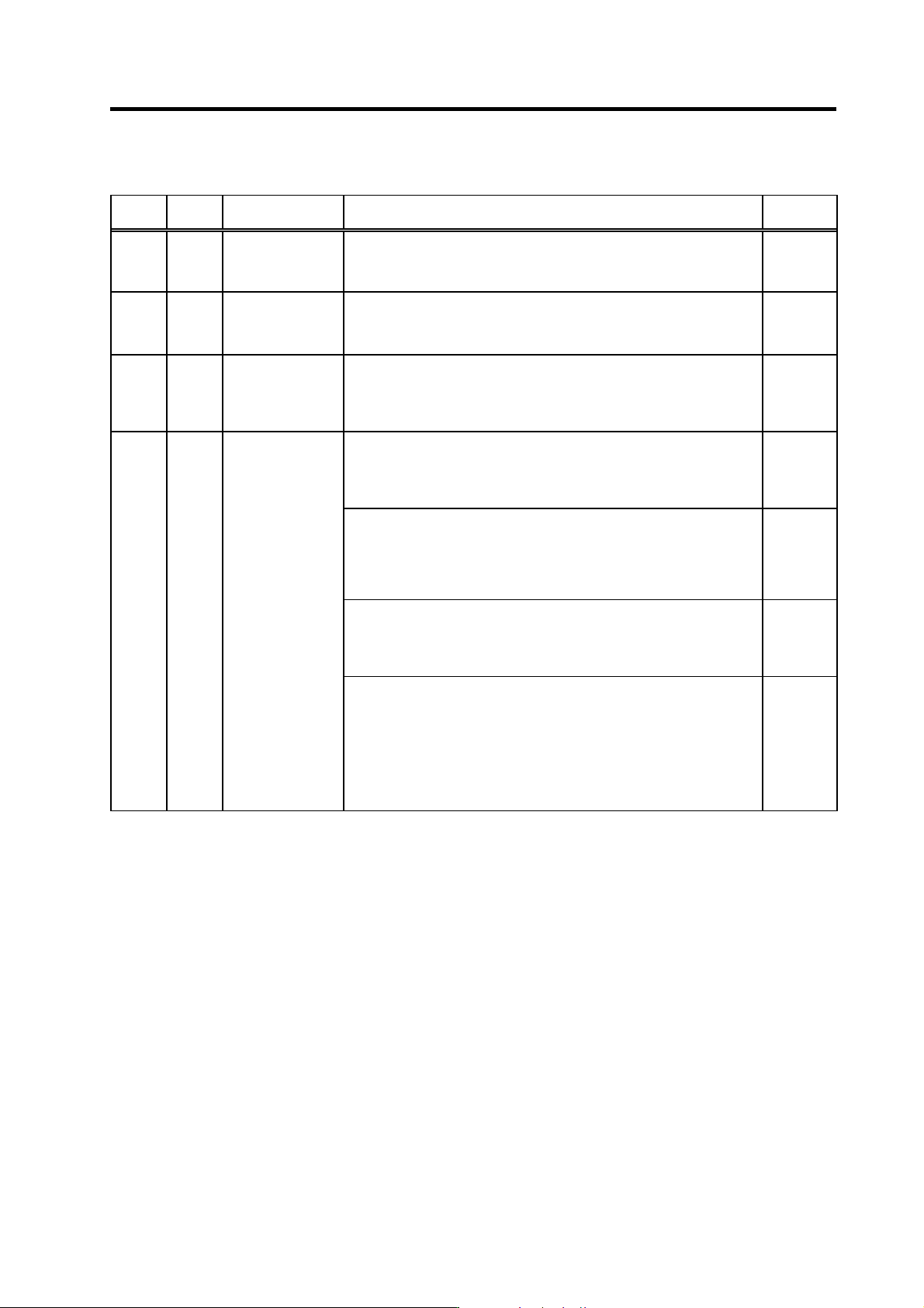
Standard specifications
No. Abbrev. Parameter name Explanation
Setting
range (Unit)
SV013 ILMT Current limit value
Set the normal current (torque) limit value. (Limit values for both + and -
direction.)
When the value is “500” (a standard setting), the maximum torque is
determined by the specification of the motor.
0 to 999
(Stall
[rated]
current %)
SV014 ILMTsp
Current limit value in
special control
Set the current (torque) limit value in a special control (initial absolute
position setting, stopper control, etc). (Limit values for both of the + and -
directions.)
Set to “500” when not using.
0 to 999
(Stall
[rated]
current %)
SV015 FFC
Acceleration rate
feed forward gain
When a relative error in the synchronous control is large, apply this
parameter to the axis that is delaying. The standard setting value is “0”.
For the SHG control, set to “100”.
To adjust a relative error in acceleration/deceleration, increase the value by
50 to 100 at a time.
0 to 999
(%)
Set this when the protrusion (that occurs due to the non-sensitive band by
friction, torsion, backlash, etc) at quadrant change is too large.
This compensates the torque at quadrant change.
This is valid only when the lost motion compensation (SV027 (SSF1.lmc))
is selected.
Type 1: When SV027 (SSF1)/bit9, 8 (lmc)=01
Set the compensation amount based on the motor torque before the
quadrant change.
The standard setting is “100”. Setting to “0” means the compensation
amount is zero.
Normally, use Type 2.
-1 to 200
(%)
Type 2: When SV027 (SSF1)/bit9, 8 (lmc)=10
Set the compensation amount based on the stall (rated) current of the
motor.
The standard setting is double of the friction torque. Setting to “0”
means the compensation amount is zero.
-1 to 200
(Stall
[rated]
current %)
SV016 LMC1
Lost motion
compensation 1
When you wish different compensation amount depending on the direction
When SV041 (LMC2) is “0”, compensate with the value of SV016
(LMC1) in both of the + and -directions.
If you wish to change the compensation amount depending on the
command direction, set this and SV041 (LMC2). (SV016: + direction,
SV041: - direction. However, the directions may be opposite
depending on other settings.)
When “-1” is set, the compensation won’t be performed in the direction of
the command.
Parameters with an asterisk * in the abbreviation, such as PC1*, are validated with the NC power turned ON again.