bnp-b2365(eng)b.pdf - 第143页
3. Setup 3 - 56 Standard specifications No. Abbrev. Parameter name Explanation Setting range (Unit) bit Explanation 8 9 A ent B Set the detector type. Set the position detector type for “pen”, and the speed detector t yp…
3. Setup
3 - 55
Standard specifications
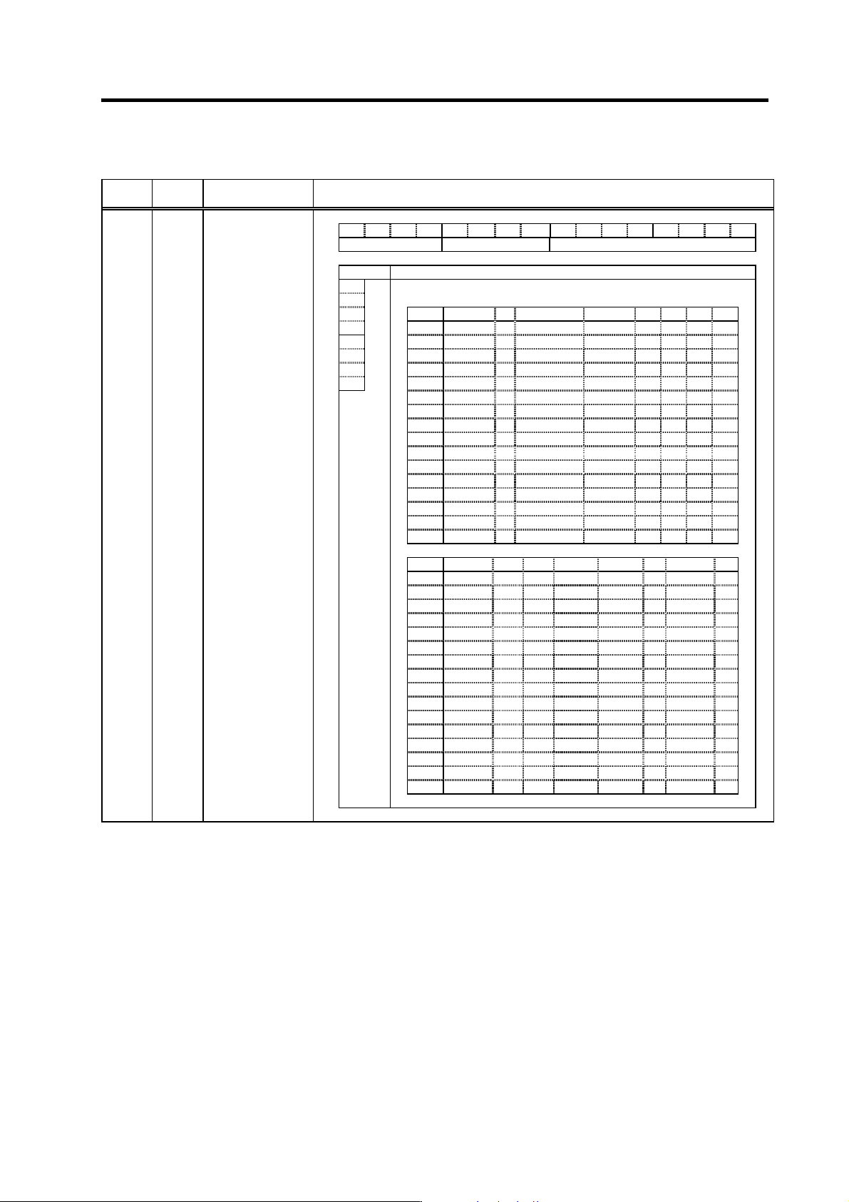
No. Abbrev. Parameter name Explanation
F E D C B A 9 8 7 6 5 4 3 2 1 0
pen ent mtyp
bit Explanation
0 Set the motor type.
1
2 Setting 0x 1x 2x 3x 4x 5x 6x 7x
3 x0 HA40N HA50L HA53L
4
mtyp
x1 HA80N HA100L HA103L
5 x2 HA100N HA200L HA203L
6 x3 HA200N HA300L HA303L
7 x4 HA300N HA500L HA503L
x5 HA700N
x6 HA900N
x7 HA-LH11K2
x8 HA-LH15K2
x9
xA HA150L HA153L
xB
xC
xD
xE
xF
Setting 8x 9x Ax Bx Cx Dx Ex Fx
x0 HA43N HC52 H53
x1 HA83N HC102 HC103 HC103R
x2 HA103N HC152 HC153 HC153R
x3 HA203N HC202 HC203 HC203R
x4 HA303N HC352 HC353 HC353R
x5 HA703N HC452 HC453 HC503R
x6 HC702 HC703
x7 HC902
x8
x9
xA HA93N
xB
xC HA053N
xD HA13N
xE HA23N
xF HA33N
SV025 MTYP*
Motor/Detector
type
Parameters with an asterisk * in the abbreviation, such as PC1*, are validated with the NC power turned ON again.
3. Setup
3 - 56
Standard specifications
No. Abbrev. Parameter name Explanation
Setting range
(Unit)
bit Explanation
8
9
A
ent
B
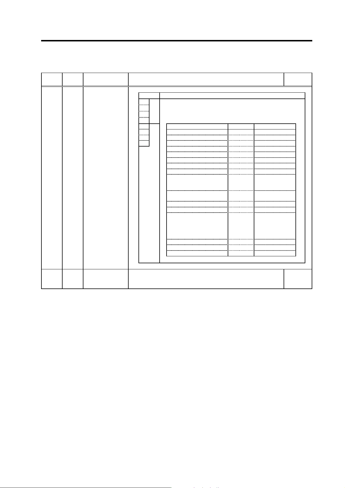
Set the detector type.
Set the position detector type for “pen”, and the speed detector type
for “ent”. In the case of the semi-closed loop control, set the same
value for “pen” and “ent”.
C Detector model name pen setting ent setting
D OSE104 0 (Note) 0
E
pen
OSA104 1 (Note) 1
F OSE105, OSA105 2 (Note) 2
3 (Note) 3
OHE25K-ET, OSE104-ET 4 Setting impossible
OHA25K-ET, OSA104-ET 5 Setting impossible
OSE105-ET, OSA105-ET 6 Setting impossible
7 Setting impossible
Relative position detection
scale, MP type (Mitsubishi
Heavy Industries)
8 Setting impossible
AT41 (Mitsutoyo), FME type,
FLE type (Futaba)
9 Setting impossible
AT342 (Mitsutoyo) A Setting impossible
B Setting impossible
The setting of the slave axis in
the speed/current
synchronization control.
When the master axis is the
semi-closed control .
C
C
(Current
synchronization)
D Setting impossible
E Setting impossible
F Setting impossible
(Note) Setting for semi-closed loop control
SV025 MTYP*
Motor/Detector
type
SV026 OD2
Excessive error
detection width
during servo OFF
Set the excessive error detection width when servo ON.
For the standard setting, refer to the explanation of SV023 (OD1).
When “0” is set, the excessive error detection will not be performed.
0 to 32767
(mm)
Parameters with an asterisk * in the abbreviation, such as PC1*, are validated with the NC power turned ON again.
3. Setup
3 - 57
Standard specifications
No. Abbrev. Parameter name Explanation
Setting range
(Unit)
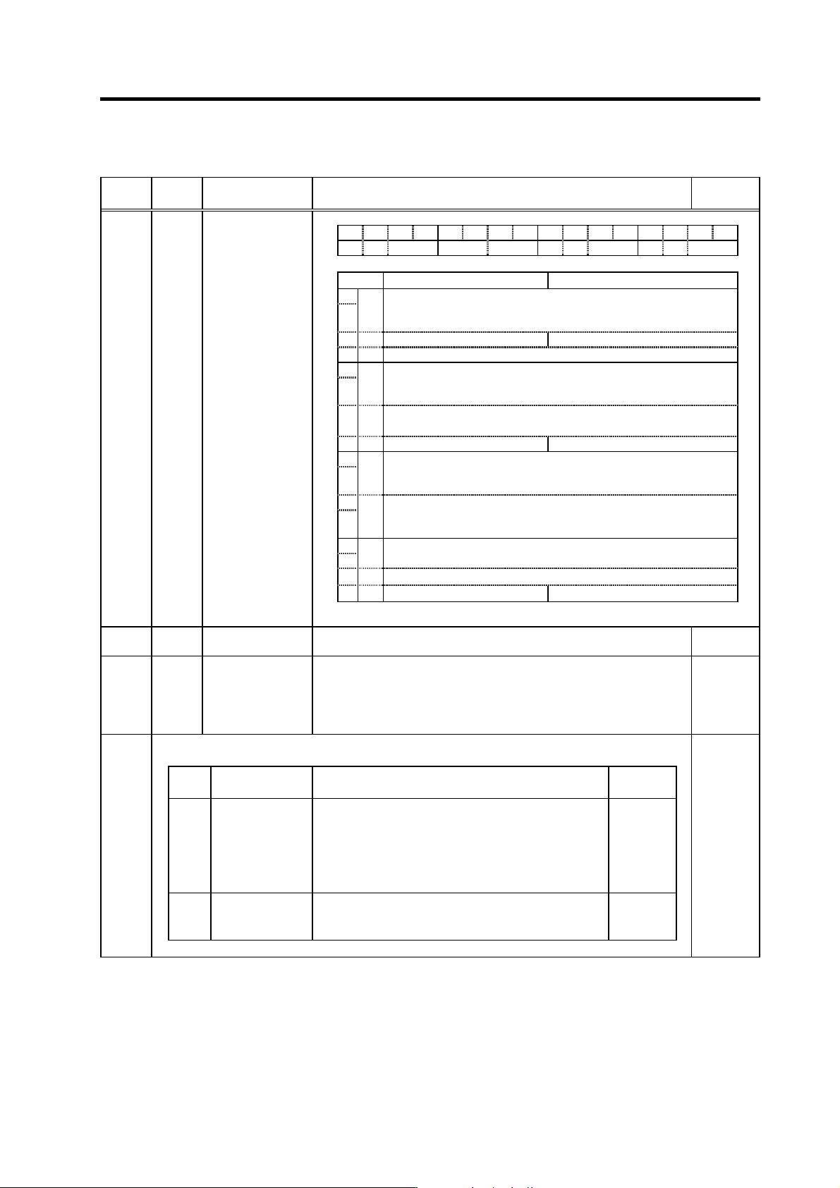
F E D C B A 9 8 7 6 5 4 3 2 1 0
aflt zrn2 afse ovs lmc zrn3 vfct upc vcnt
bit Meaning when “0” is set Meaning when “1” is set
0
1
vcnt
Set the execution changeover type of the speed loop delay compensation.
00: Delay compensation changeover invalid
10: Delay compensation type 2
01: Delay compensation changeover type 1
11: Setting prohibited
2 upc Starting torque compensation invalid Starting torque compensation valid
3
4
5
vfct
Set the number of compensation pulses of the jitter compensation.
00: Jitter compensa tion invalid
10: Jitter compensation 2 pulse s
01: Jitter compensation 1 pulse
11: Jitter compensation 3 pulses
6zrn3
ABZ scale: Set to "1" to fix Z-phase detection edge.
Absolute position scale: Set to "1" in using AT342.
7 omr Machine end compensation invalid Machine end compensation valid
8
9
lmc
Set the compensation amount w ith SV016 (LMC1) and SV041 (LMC2).
00: Lost motion compensation stop
10: Lost motion compensation type 2
01: Lost motion compensation ty pe 1
11: Setting prohibited
A
B
ovs
Set the compensation amount with SV031 (OVS1) and SV042 (OVS2).
00: Overshooting compensation stop
10: Overshooting compensation ty pe 2
01: Overshooting compensation ty pe 1
11: Setting prohibited
C 00: Adaptive filter sensitivity standard
D
afse
11: Adaptive filter sensitivity increase (Set 2bits at a time)
E zrn2 Set to “1”.
F aflt Adaptive filter stop Adaptive filter start
SV027 SSF1
Servo function
selection 1
(Note) Set to "0" for bits with no particular description.
SV028
Not used. Set to "0". 0
SV029 VCS
Speed at the
change of speed
loop gain
If the noise is bothersome at high speed during rapid traverse, etc, lower
the speed loop gain.
Set the speed at which the speed loop gain changes, and use this with
SV006 (VGN2).
When not using, set to “0”.
0 to 9999
(r/min)
The higher order 8bits and lower order 8bits are used for different functions.
“The setting value of SV030” = (Icx × 256) + IVC
Abbrev. Parameter name Explanation
Setting range
(Unit)
IVC
(Low
order)
Voltage dead band
compensation
When 100% is set, the voltage equivalent to the logical
non-energized time will be compensated.
When “0” is set, a 100% compensation will be performed.
Adjust in increments of 10% from the default value 100%.
If increased too much, vibration or vibration noise may be
generated.
0 to 255
(%)
Icx
(High
order)
Current bias 1
Normally set to “0”.
Use this in combination with SV040 and the high order
8bits of SV045.
0 to 127
SV030
0 to 32767
Parameters with an asterisk * in the abbreviation, such as PC1*, are validated with the NC power turned ON again.