bnp-b2365(eng)b.pdf - 第147页
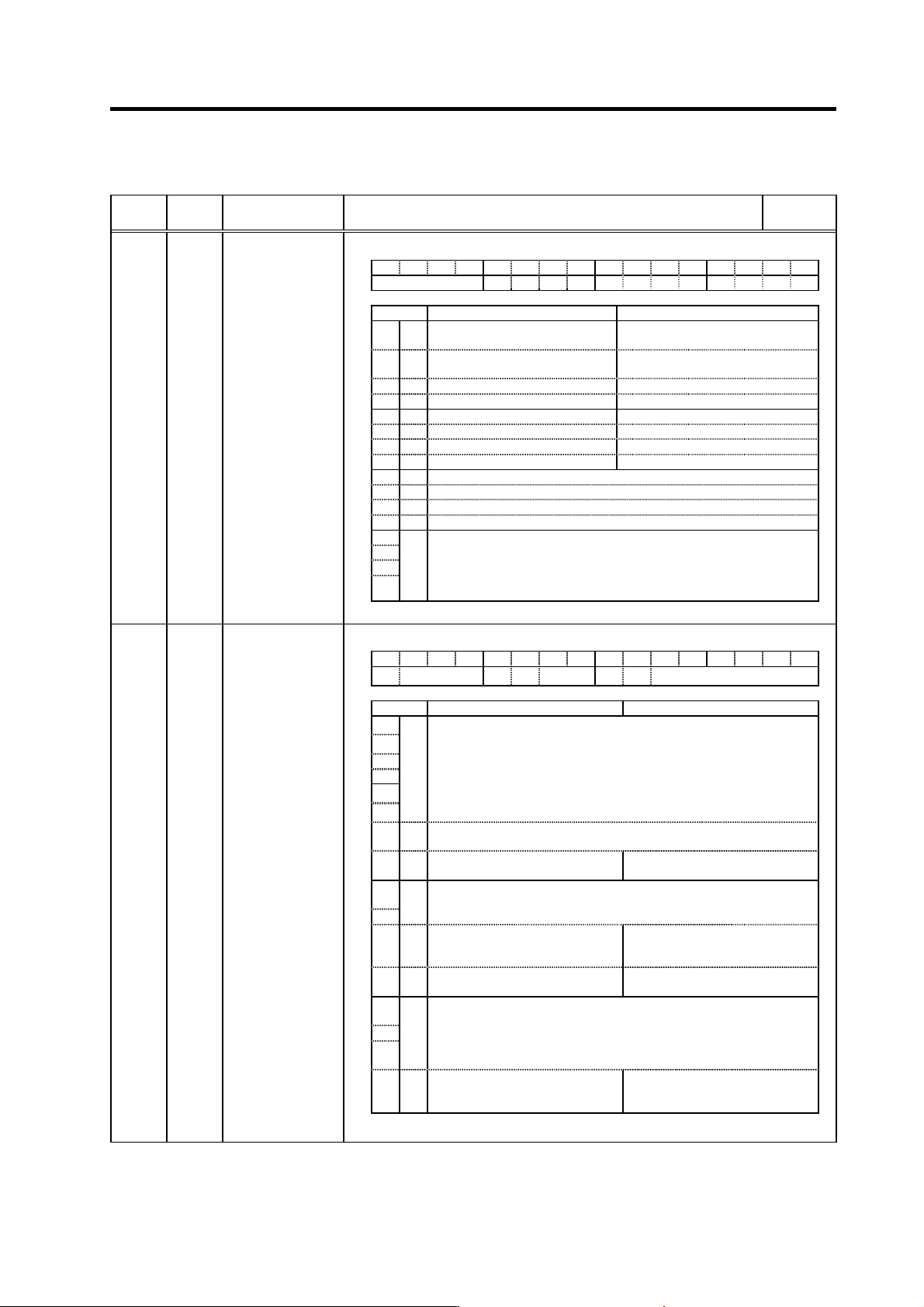
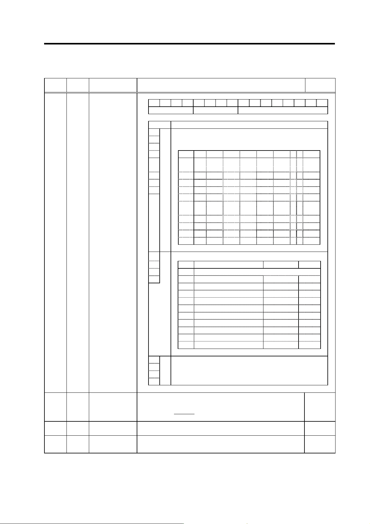
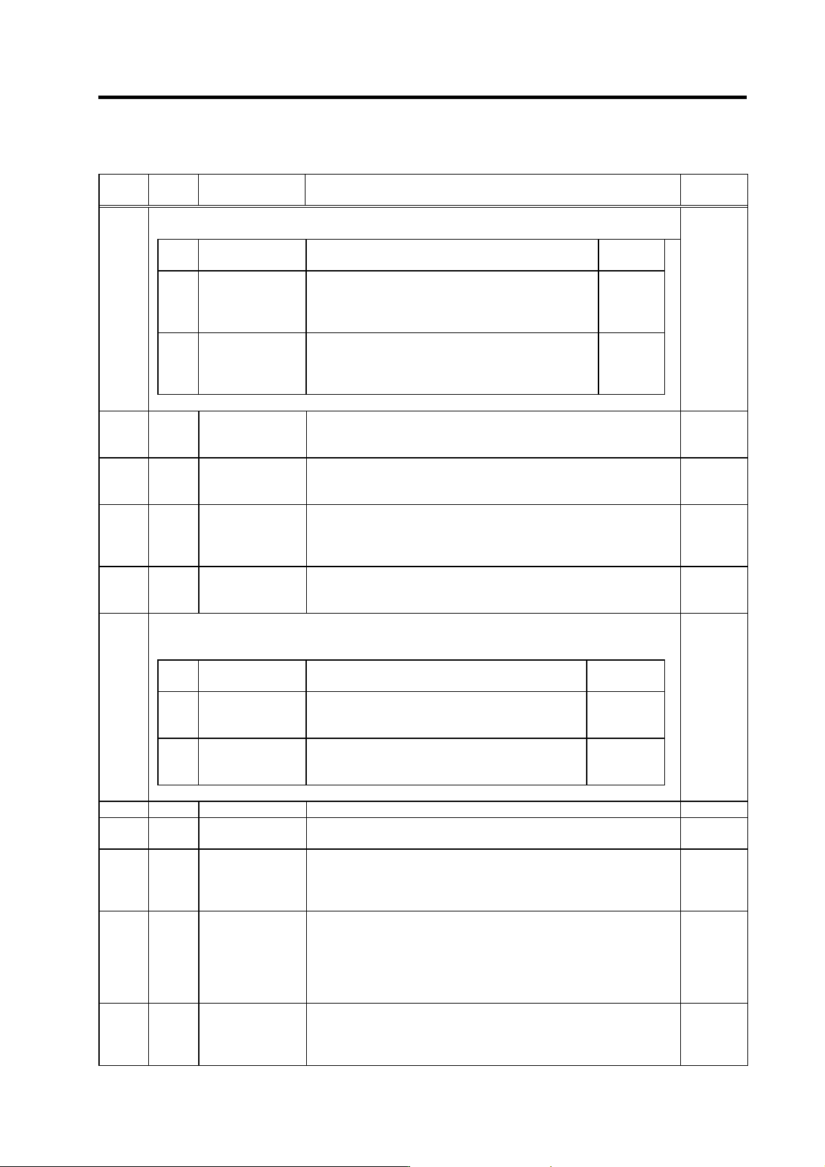
3. Setup 3 - 60 Standard specifications No. Abbrev. Parameter name Explanation Setting range (Unit) F E D C B A 9 8 7 6 5 4 3 2 1 0 amp rtyp ptyp bit Explanation 0 1 When the CN4 connector of the drive unit and the po we…
3. Setup
3 - 59
Standard specifications
No. Abbrev. Parameter name Explanation
S
etting range
(Unit)
FEDCBA98765 4 3 2 10
ovsn has2 has1
bit Meaning when “0” is set Meaning when “1” is set
0 has1
Setting for normal use.
(Except for HC)
HAS control 1 valid
(HC: High acceleration rate support)
1 has2
Setting for normal use.
(Except for HC)
HAS control 2 valid
(HC: Overshooting support)
2
3
4
5
6
7
8
9
A
B
C
D
E
ovsn
F
Set the non-sensitive band of the overshooting compensation type 3 in
increments of 2m at a time.
In the feed forward control, the non-sensitive band of the model
position droop is set, and overshooting of the model is ignored. Set
2µm (0001) as a standard.
SV034 SSF3
Servo function
selection 3
(Note) Set to “0” for bits with no particular description.
HEX setting
FEDCBA98765 4 3 2 10
clt clG1 cl2n clet cltq iup tdt
bit Meaning when “0” is set Meaning when “1” is set
0
1
2
3
4
5
tdt
Td creation time setting
Set to “0”. (For machine tool builder adjustment)
6iup
Set to “1” when using any of motors from HC152 to HC702 and from
HC153 to HC453.
7 ckab
Setting for normal use No signal 2 (Alarm 21) special
detection
8
Set the retracting torque for collision detection in respect to the
maximum torque of the motor.
9
Cltq
00: 100% 01: 90% 10: 80% (Standard) 11: 70%
Aclet
Setting for normal use The disturbance torque peak of the
latest two seconds is displayed in
MPOS of the servo monitor screen.
B cl2n Collision detection method 2 valid
Collision detection method 2
invalid
C
Collision detection method 1
Set the collision detection level during cutting feed (G1).
D clG1 The G1 collision detection level=SV060*clG1.
E
When clG1=0, the collision detection method 1 during cutting feed
won’t function.
Fclt
Setting for normal use The guide value of the SV059
setting value is displayed in MPOS
of the servo monitor screen.
SV035 SSF4
Servo function
selection 4
(Note) Set to “0” for bits with no particular description.
Parameters with an asterisk * in the abbreviation, such as PC1*, are validated with the NC power turned ON again.
3. Setup
3 - 60
Standard specifications
No. Abbrev. Parameter name Explanation
Setting range
(Unit)
F E D C B A 9 8 7 6 5 4 3 2 1 0
amp rtyp ptyp
bit Explanation
0
1
When the CN4 connector of the drive unit and the power supply are
connected, setting below is necessary.
2 To validate the external emergency stop function, add 40h.
3 Setting 0x 1x 2x 3x 4x 5x 6x 7x 8x
4
ptyp
x0
Not
used
CV-300
5 x1 CV-110 CR-10
6 x2 CV-220 CR-15
7 x3 CR-22
x4 CV-3
7
CR-37
x5 CV-150
MDS-B-
CVE-450
MDS-B-
CVE-550
x6 CV-5
5
CV-260 CR-55
x7 CV-370
x8 CV-7
5
CR-75
x9 CV-185 CR-90
8
Set the regenerative resistor type when MDS-A-CR is used.
9
Setting Regenerative resistor model name Resistance value Capacity
A
0 MDS-C1-CV (Setting when using power supply regeneration)
B
rtyp
1 GZG200W260HMJ
26
Ω
80W
2
GZG300W130HMJ×2
26
Ω
150W
3 MR-RB30
13
Ω
300W
4 MR-RB50
13
Ω
500W
5 GZG200W200HMJ × 3
6.7
Ω
350W
6 GZG300W200HMJ × 3
6.7
Ω
500W
7 R-UNIT-1
30
Ω
700W
8 R-UNIT-2
15Ω
700W
9 R-UNIT-3
15Ω
2100W
A to F No setting
C Always set "0".
D
E
amp
F
SV036 PTYP*
Power supply type
Set “the motor inertia + motor axis conversion load inertia” in respect to the
motor inertia.
Jl+Jm Jm Motor inertia
SV037 JL
Load inertia scale
SV037(JL) =
Jm
×100
Jl Motor axis conversion load inertia
0 to 5000
(%)
SV038 FHz1
Notch filter
frequency 1
Set the vibration frequency to suppress if machine vibration occurs.
(Valid at 36 or more) When not using, set to “0”.
0 to 3000
(Hz)
SV039 LMCD
Lost motion
compensation
timing
Set this when the lost motion compensation type2 timing doest not match.
Adjust by increasing the value by 10 at a time.
0 to 2000
(ms)
Parameters with an asterisk * in the abbreviation, such as PC1*, are validated with the NC power turned ON again.
3. Setup
3 - 61
Standard specifications
No. Abbrev. Parameter name Explanation
Setting range
(Unit)
For SV040, the hex. value’s higher order 8bits and lower order 8bits are used for different functions.
“Setting value of SV040” = (Icy*256) + LMCT
Abbrev. Parameter name Explanation
Setting range
(Unit)
LMCT
(Low
order)
Lost motion
compensation dead
band
Set the dead band of the lost motion compensation in the
feed forward control.
When “0” is set, the actual value that is set is 2m.
Adjust by increasing by 1m at a time.
0 to 100
(µm)
Icy
(High
order)
Current bias 2
Normally, set to “40” if you use HC202 to HC902, HC203
to HC703.
Use this in combination with SV030 and the high order
8bits of SV045.
0 to 127
SV040
0 to 32767
SV041 LMC2
Lost motion
compensation 2
Set this with SV016 (LMC1) only when you wish to set the lost motion
compensation amount to be different depending on the command directions.
Set to “0” as a standard.
-1 to 200
(Stall [rated]
current %)
SV042 OVS2
Overshooting
compensation 2
Set this with SV031 (OVS1) only when you wish to set the overshooting
compensation amount to be different depending on the command directions.
Set to “0” as a standard.
-1 to 100
(Stall [rated]
current %)
SV043 OBS1
Disturbance
observer filter
frequency
Set the disturbance observer filter band.
Set to “100” as a standard.
To use the disturbance observer, also set SV037 (JL) and SV044 (OBS2).
When not using, set to “0”.
0 to 1000
(rad/s)
SV044 OBS2
Disturbance
observer gain
Set the disturbance observer gain. The standard setting is “100” to “300”.
To use the disturbance observer, also set SV037 (JL) and SV043 (OBS1).
When not using, set to “0”.
0 to 500
(%)
For SV045, the hexadecimal value's higher order 8 bits and lower order 8 bits are used for different
functions.
“Setting value of SV045” = (Icy
× 256) + LMCT
Abbrev. Parameter name Explanation
Setting range
(Unit)
TRUB
(Low
order)
Frictional torque
When you use the collision detection function, set the
frictional torque.
0 to 100
(Stall [rated]
current %)
Ib1
(High
order)
Current bias 3
Normally set to “0”.
Use this in combination with SV030 and the high order
8bits of SV040.
0 to 127
SV045
0 to 32767
SV046 Not used. Set to "0". 0
SV047 EC
Inductive voltage
compensation gain
Set the inductive voltage compensation gain. Set to “100” as a standard.
If the current FB peak exceeds the current command peak, lower the gain.
0 to 200
(%)
SV048 EMGrt
Vertical axis drop
prevention time
Input a length of time to prevent the vertical axis from dropping by delaying
Ready OFF until the brake works when the emergency stop occurs.
Increase the setting by 100msec at a time and set the value where the axis
does not drop.
0 to 20000
(ms)
SV049 PGN1sp
Position loop gain 1
in spindle
synchronous control
Set the position loop gain during the spindle synchronous control
(synchronous tapping, synchronous control with spindle/C axis).
Set the same value as the value of the spindle parameter, position loop gain
in synchronous control.
When performing the SHG control, set this with SV050 (PGN2sp) and
SV058 (SHGCsp).
1 to 200
(rad/s)
SV050 PGN2sp
Position loop gain 2
in spindle
synchronous control
Set this with SV049 (PGN1sp) and SV058 (SHGCsp) if you wish to perform
the SHG control in the spindle synchronous control (synchronous tapping,
synchronous control with spindle/C axis).
When not performing the SHG control, set to “0”.
0 to 999
(rad/s)
Parameters with an asterisk * in the abbreviation, such as PC1*, are validated with the NC power turned ON again.