bnp-b2365(eng)b.pdf - 第149页
3. Setup 3 - 62 Standard specifications No. Abbrev. Parameter name Explanation Setting range (Unit) SV051 DFBT Dual feed back control time constant Set the control time constant in dual feed back. When “0” is set, the ac…
3. Setup
3 - 61
Standard specifications
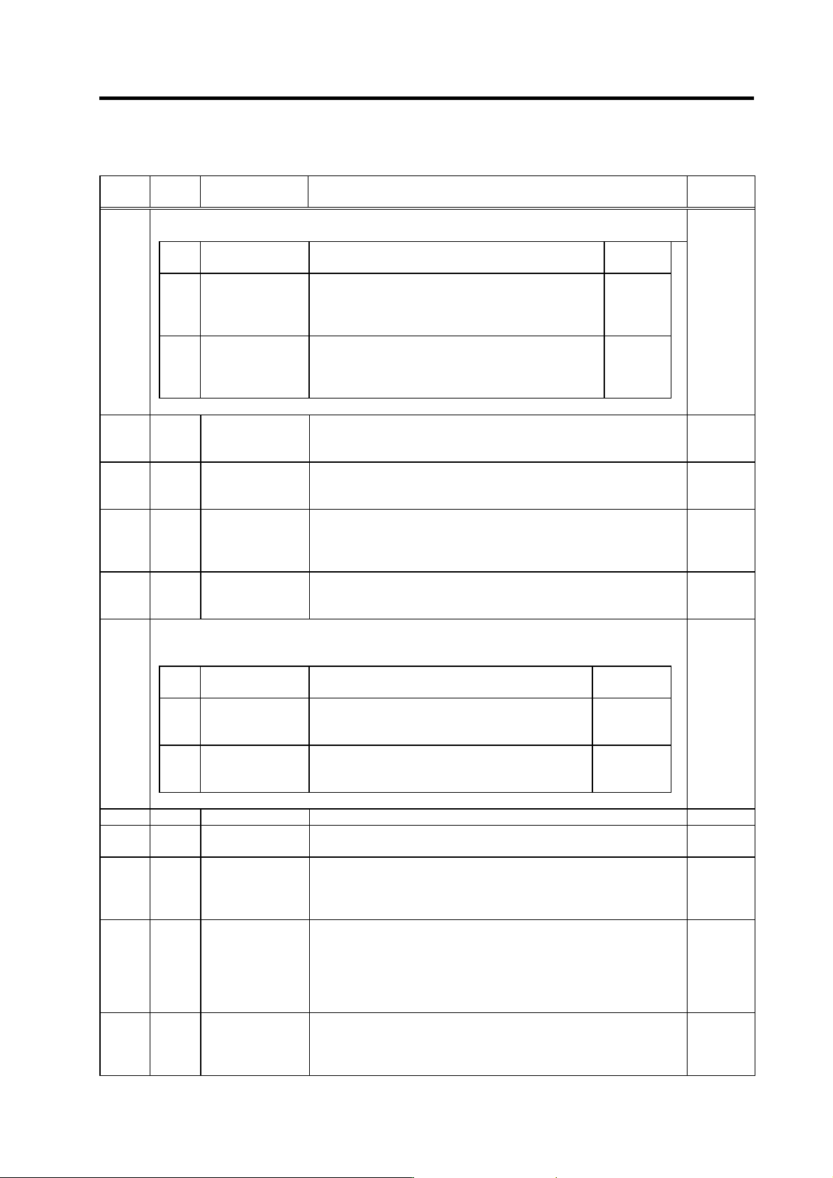
No. Abbrev. Parameter name Explanation
Setting range
(Unit)
For SV040, the hex. value’s higher order 8bits and lower order 8bits are used for different functions.
“Setting value of SV040” = (Icy*256) + LMCT
Abbrev. Parameter name Explanation
Setting range
(Unit)
LMCT
(Low
order)
Lost motion
compensation dead
band
Set the dead band of the lost motion compensation in the
feed forward control.
When “0” is set, the actual value that is set is 2m.
Adjust by increasing by 1m at a time.
0 to 100
(µm)
Icy
(High
order)
Current bias 2
Normally, set to “40” if you use HC202 to HC902, HC203
to HC703.
Use this in combination with SV030 and the high order
8bits of SV045.
0 to 127
SV040
0 to 32767
SV041 LMC2
Lost motion
compensation 2
Set this with SV016 (LMC1) only when you wish to set the lost motion
compensation amount to be different depending on the command directions.
Set to “0” as a standard.
-1 to 200
(Stall [rated]
current %)
SV042 OVS2
Overshooting
compensation 2
Set this with SV031 (OVS1) only when you wish to set the overshooting
compensation amount to be different depending on the command directions.
Set to “0” as a standard.
-1 to 100
(Stall [rated]
current %)
SV043 OBS1
Disturbance
observer filter
frequency
Set the disturbance observer filter band.
Set to “100” as a standard.
To use the disturbance observer, also set SV037 (JL) and SV044 (OBS2).
When not using, set to “0”.
0 to 1000
(rad/s)
SV044 OBS2
Disturbance
observer gain
Set the disturbance observer gain. The standard setting is “100” to “300”.
To use the disturbance observer, also set SV037 (JL) and SV043 (OBS1).
When not using, set to “0”.
0 to 500
(%)
For SV045, the hexadecimal value's higher order 8 bits and lower order 8 bits are used for different
functions.
“Setting value of SV045” = (Icy
× 256) + LMCT
Abbrev. Parameter name Explanation
Setting range
(Unit)
TRUB
(Low
order)
Frictional torque
When you use the collision detection function, set the
frictional torque.
0 to 100
(Stall [rated]
current %)
Ib1
(High
order)
Current bias 3
Normally set to “0”.
Use this in combination with SV030 and the high order
8bits of SV040.
0 to 127
SV045
0 to 32767
SV046 Not used. Set to "0". 0
SV047 EC
Inductive voltage
compensation gain
Set the inductive voltage compensation gain. Set to “100” as a standard.
If the current FB peak exceeds the current command peak, lower the gain.
0 to 200
(%)
SV048 EMGrt
Vertical axis drop
prevention time
Input a length of time to prevent the vertical axis from dropping by delaying
Ready OFF until the brake works when the emergency stop occurs.
Increase the setting by 100msec at a time and set the value where the axis
does not drop.
0 to 20000
(ms)
SV049 PGN1sp
Position loop gain 1
in spindle
synchronous control
Set the position loop gain during the spindle synchronous control
(synchronous tapping, synchronous control with spindle/C axis).
Set the same value as the value of the spindle parameter, position loop gain
in synchronous control.
When performing the SHG control, set this with SV050 (PGN2sp) and
SV058 (SHGCsp).
1 to 200
(rad/s)
SV050 PGN2sp
Position loop gain 2
in spindle
synchronous control
Set this with SV049 (PGN1sp) and SV058 (SHGCsp) if you wish to perform
the SHG control in the spindle synchronous control (synchronous tapping,
synchronous control with spindle/C axis).
When not performing the SHG control, set to “0”.
0 to 999
(rad/s)
Parameters with an asterisk * in the abbreviation, such as PC1*, are validated with the NC power turned ON again.
3. Setup
3 - 62
Standard specifications
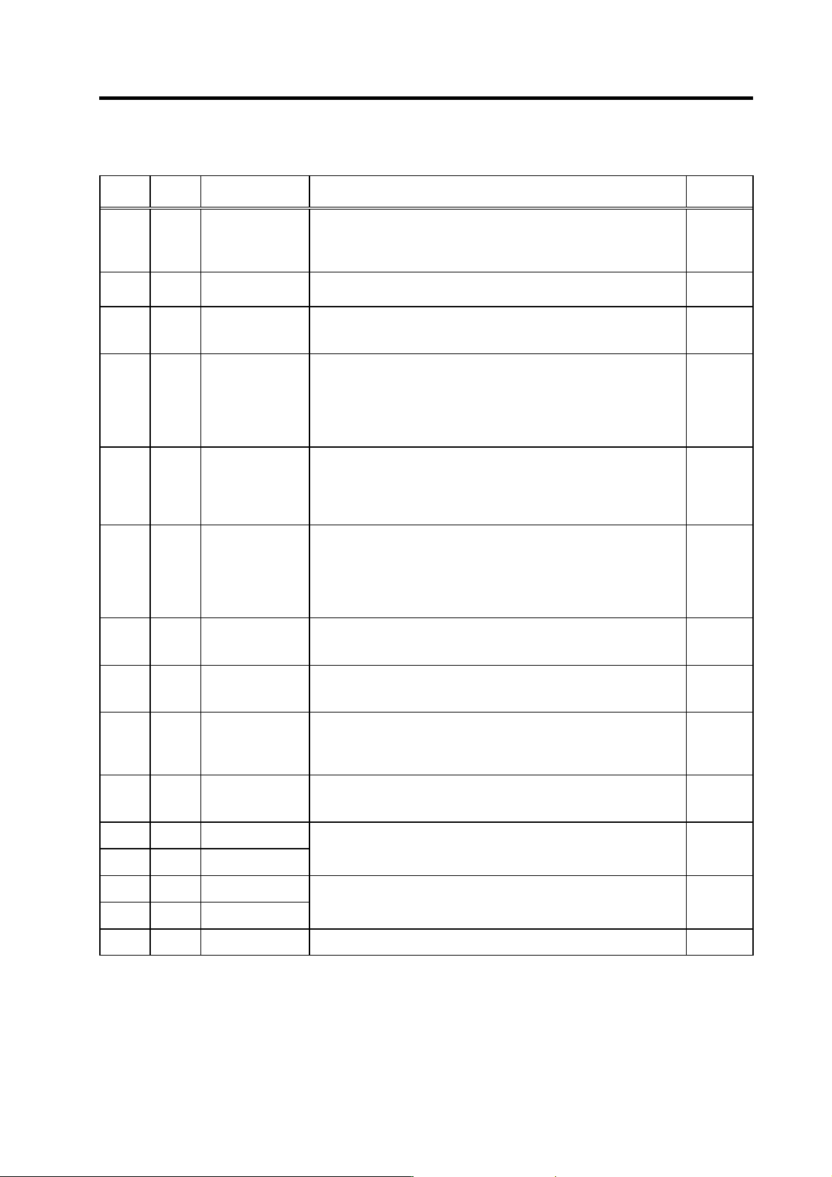
No. Abbrev. Parameter name Explanation
Setting range
(Unit)
SV051
DFBT
Dual feed back
control time
constant
Set the control time constant in dual feed back.
When “0” is set, the actual value that is set is 1ms.
The higher the time constant is, t he closer it gets to the semi-closed control,
so the limit of the position loop gain is raised.
0 to 9999
(ms)
SV052
DFBN
Dual feedback
control dead zone
Set to “0” as a standard.
Set the dead zone in the dual feedback control.
0 to 9999
(µm)
SV053 OD3
Excessive error
detection width in
special control
Set the excessive error detection width when servo ON in a special control
(initial absolute position setting, stopper control, etc.).
If “0” is set, excessive error detection won’t be performed.
0 to 32767
(mm)
SV054 ORE
Overrun detection
width in closed loop
control
Set the overrun detection width in the full-closed loop control.
If the gap between the motor end detector and the linear scale (tool end
detector) exceeds the value set by this parameter, it is judged to be overrun
and Alarm 43 will be detected.
When “-1” is set, the alarm detection won’t be performed. When “0” is set,
overrun is detected with a 2mm width.
-1 to 32767
(mm)
SV055
EMGx
Max. gate off delay
time after
emergency stop
Set a length of time from the point when the emergency stop is input to the
point when READY OFF is compulsorily executed.
Normally, set the same value as the absolute value of SV056.
In preventing the vertical axis from dropping, the gate off is delayed for the
length of time set by SV048 if SV055’s value is smaller than that of SV048.
0 to 20000
(ms)
SV056 EMGt
Deceleration time
constant at
emergency stop
Set the time constant used for the deceleration control at emergency stop.
Set a length of time that takes from rapid traverse rate (rapid) to stopping.
Normally, set the same value as the rapid traverse acceleration/deceleration
time constant.
When executing the synchronous operation, put the minus sign to the
settings of both of the master axis and slave axis.
-20000 to
20000
(ms)
SV057 SHGC
SHG control gain
When performing the SHG control, set this with S003 (PGN1) and SV004
(PGN2).
When not performing the SHG control, set to “0”.
0 to 999
(rad/s)
SV058 SHGCsp
SHG control gain in
spindle
synchronous control
Set this with SV049 (PGN1sp) and SV050 (PGN2sp) if you wish to perform
the SHG control in the synchronous tapping control.
When not performing the SHG control, set to “0”.
0 to 999
(rad/s)
SV059 TCNV
Collision detection
torque estimating
gain
Set the torque estimating gain when using the collision detection function.
After setting as SV035/bitF(clt)=1 and performing acceleration/deceleration,
set the value displayed in MPOS of the NC servo monitor screen.
Set to “0” when not using the collision detection function.
-32768 to
32767
SV060 TLMT
Collision detection
level
When using the collision detection function, set the collision detection level
during the G0 feeding.
If “0” is set, none of the collision detection function will work.
0 to 999
(Stall [rated]
current %)
SV061 DA1NO
D/A output channel
1 data No.
SV062 DA2NO
D/A output channel
2 data No.
Input the data number you wish to output to D/A output channel.
In the case of MDS-C1-V2, set the axis on the side to which the data will not
be output to “-1”.
-1 to 127
SV063 DA1MPY
D/A output channel
1 output scale
SV064 DA2MPY
D/A output channel
2 output scale
Set the scale with a 1/256 unit.
When “0” is set, output is done with the standard output unit.
-32768 to
32767
(Unit: 1/256)
SV065
Not used. Set to "0".
0
Parameters with an asterisk * in the abbreviation, such as PC1*, are validated with the NC power turned ON again.

3. Setup
3 - 63
3-4 Restrictions on servo control
There may be some restrictions on mechanical specifications and electrical specifications when
executing servo controls. Always read this section when designing machines and confirm that no
problems exist with the specifications.
3-4-1 Restrictions of electronic gear setting value
The servo drive unit has internal electronic gears. The command value from the NC is converted into a
detector resolution unit to carry out position control. The electronic gears are single gear ratios
calculated from multiple parameters as shown below, and each value (ELG1, ELG2) must be 32767 or
less.
If the value overflows, the initial parameter error (alarm 37) or error parameter No. 101 (2301 with
M60S/E60 Series NC) will be output.
If an alarm occurs, the mechanical specification s and electrical specificatio ns (such as resol ution of the
detector) must be revised so that the electronic ge ars are within the specification s ran ge.
(1) For semi-closed loop control
ELG1
PC2×RNG1
Reduced fraction of
ELG2
=
PC1×PIT×IUNIT
(reduced fraction)
IUNIT = 2/NC command unit (µm)
1µm : IUNIT = 2, 0.1µm : IUNIT = 20
When the above is calculated, the following conditions must be satisfied.
ELG1 ≤ 32767
ELG2 ≤ 32767
(2) For full-closed loop control
PGNX
PC2×RNG2×PGN1
Reduced fraction of
PGNY
=
PC1×RNG1×30
(reduced fraction)
When the above is calculated, the following conditions must be satisfied.
PGNX ≤ 32767
PGNY ≤ 32767
And,
PGNXsp
PC2×RNG2×PGN1sp
Reduced fraction of
PGNYsp
=
PC1×RNG1×30
(reduced fraction)
When the above is calculated, the following conditions must be satisfied.
PGNXsp ≤ 32767
PGNYsp ≤ 32767
POINT
If the electronic gears overflow, the alarm 37 or error parameter No . 101 (2301
with M60S/E60 series NC) will be output.