bnp-b2365(eng)b.pdf - 第154页
3. Setup 3 - 67 M60S Series No. Abbrev . Parameter name Det ails Setting rang e (Unit) 3021 sori Orientation rotation speed Set the spindle orientation rotation speed. Set the rotation speed for when the spindle rotates …
3. Setup
3 - 66
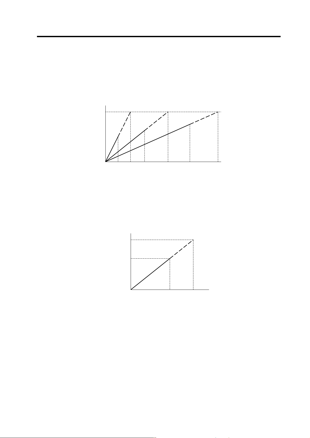
<Relation of spindle limit rotation speed and spindle maximum rotation speed>
The spindle rotation speed which can be attained at the spindle motor's maximum rotation speed is
set for the limit rotation speed (slimt). This value is obtained by multiplying the gear ratio on the
spindle motor maximum rotation speed (SP017). Set the maximum rotation speed (smax) when
the rotation speed is to be limited according to the machine specifications, such as the spindle gear
specifications. Up to four value can be set for gear changeover.
<Relation of tap time constant and actual acceleration/deceleration time constant>
(For constant inclination synchronous tap cycle)
Set the acceleration time up to the tap rotation speed (stap) in the tap time constant (stapt).
Acceleration/deceleration is carried out at the same inclination for all speed commands. Up to four
values can be set for gear changeover.
SP017
Spindle motor rotation speed
(r/min)
0
smax1 slimt1 smax2 smax(n)slimt2 slimt(n)
Spindle rotation speed (r/min)
stap(n)
0
Actual time
stapt(n)
Time (ms)
Actual
command
Spindle speed (r/min)

3. Setup
3 - 67
M60S
Series
No.
Abbrev. Parameter name Details
Setting range
(Unit)
3021 sori
Orientation
rotation speed
Set the spindle orientation rotation speed.
Set the rotation speed for when the spindle rotates at the constant
rotation speed.
0 to 32767
(r/min)
3022 sgear
Encoder gear ratio Set the gear ratio of the spindle to the spindle end detector when the
spindle end detector feed back is directly input to NC.
0: 1/1
1: 1/2
2: 1/4
3: 1/8
3023 smini
Minimum rotation
speed
Set the minimum rotation speed of the spindle.
If an S command instructs the rotation speed below this setting, the
spindle rotates at the minimum rotation speed set by this parameter.
0 to 32767
(r/min)
3024 sout*
Spindle
connection
Set the type of the spindle to be connected.
0: No connection with the spindle
1: Serial connection (bus)
2 to 5: Analog output
0 to 5
3025 enc-on
Spindle end
detector
Set the spindle end detector connection destination.
0: No connection
1: NC
2: Drive unit
0 to 2
3026 cs_ori
Selection of coil in
orientation mode
0: Perform orientation using the coil selected when the orientation
command is issued.
1: Use coil L whenever the orientation command is issued.
0/1
3027 cs_syn
Selection of coil in
spindle
synchronous
mode
0: The coil H/L is selected by the actual spindle motor rotation speed
(calculated from commanded rotation speed) when spindle
synchronous control starts. (The coil is not switched during
synchronous control. The control is carried out with the coil selected
at start.)
If the actual spindle motor rotation speed is less than SP020, the coil
L is selected, and if more than the value, the coil H is selected.
1: Use coil H whenever the spindle synchronous command is issued.
0/1
3028 sprcmm
L system tap cycle
spindle forward
run/
reverse run M
command
Set the M code of the spindle forward run/reverse run command.
High-order three digits: The spindle forward run command's M code is
set.
Low-order three digits: The spindle reverse run command's M code is
set.
0 to 999999
3029 tapsel
Asynchronous tap
gear selection
Specify whether to use the tap rotation speed or maximum rotation
speed for the gear that is selected when an asynchronous tap command
is issued.
0: Tap rotation speed
1: Maximum rotation speed
This parameter is valid only when the M-function synchronous tap cycle
enable parameter (#1272 ext08/bit1) is ON.
0/1
3030 Not used. Set to "0". 0
3031
smcp_no *
Drive unit I/F
channel No.
(spindle)
Using a 4-digit number, set the drive unit interface channel No. and
which axis in that channel is to be used when connecting a spindle drive
unit.
High-order two digits : Drive unit interface channel No.
Low-order two digits : Axis No.
When using the conventional fixed layout, set all axes to "0000".
Set "0000" when using an analog spindle.
0000
0101 to 0107
0201 to 0207
3032
Not used. Set to "0". 0
Parameters with an asterisk * in the abbreviation, such as sout*, are validated with the NC power turned ON again.

3. Setup
3 - 68
M60S
Series
No.
Abbrev. Parameter name Details
Setting range
(Unit)
3037
3038
3039
3040
taps 21
22
23
24
Synchronous tap
switching spindle
speed 2
Set the spindle rotation speed at which the step-2
acceleration/deceleration time constant is to be switched at gear 00, 01,
10, or 11.
0 to 99999
(r/min)
3041
3042
3043
3044
tapt 21
22
23
24
Synchronous tap
switching time
constant 2
Set the time constant to reach synchronous tap switching spindle
rotation speed 2 (taps 21 to 24) at gear 00, 01, 10, or 11.
1 to 5000 (ms)
3045
3046
3047
3048
tapt 31
32
33
34
Synchronous tap
switching time
constant 3
Set the time constant to reach the maximum rotation speed (smax 1 to 4)
at gear 00, 01, 10, or 11.
1 to 5000 (ms)
3049 spt
Spindle
synchronization
acceleration/
deceleration time
constant
Set the acceleration/deceleration time constant for when the spindle
synchronization command's rotation speed changes during spindle
synchronous control.
0 to 9999 (ms)
3050 sprlv
Spindle synchro-
nization rotation
speed attainment
level
The spindle rotation speed synchronization complete signal will turn ON
when the difference of the reference spindle and synchronous spindle
actual rotation speeds is less than the level set for the synchronous
spindle rotation speed command value during spindle synchronous
control.
0 to 4095
(pulse)
(1 pulse =
0.088°)
3051 spplv
Spindle phase
synchronization
attainment level
The spindle phase synchronization complete signal will turn ON when
the phase difference of the reference spindle and synchronous spindle is
less than the set level during spindle phase synchronization control.
0 to 4095
(pulse)
(1 pulse =
0.088°)
3052 spplr
Spindle motor
spindle relative
polarity
Set the spindle motor and spindle's relative polarity.
Spindle CW rotation at motor CW rotation: Positive polarity Spindle CCW
rotation at motor CW rotation: Negative polarity
0: Positive
polarity
1: Negative
polarity
3053 sppst
Spindle end
detector
Z -phase position
Set the deviation amount from the spindle's reference position to the
spindle end detector's Z phase.
The deviation amount is obtained using the clockwise direction looking
from the front of the spindle as the positive direction.
0 to 359999
(1/1000°)
3054 sptc1
Spindle synchro-
nization multi-step
acceleration/
deceleration
changeover
speed 1
Set the spindle speed for changing the 1st step's
acceleration/deceleration time constant.
0 to 99999
(r/min)
3055 sptc2
Spindle synchro-
nization multi-step
acceleration/
deceleration
changeover
speed 2
Set the spindle speed for changing the 2nd step's
acceleration/deceleration time constant.
0 to 99999
(r/min)
3056 sptc3
Spindle synchro-
nization multi-step
acceleration/
deceleration
changeover
speed 3
Set the spindle speed for changing the 3rd step's
acceleration/deceleration time constant.
0 to 99999
(r/min)
3057 sptc4
Spindle synchro-
nization multi-step
acceleration/
deceleration
changeover
speed 4
Set the spindle speed for changing the 4th step's
acceleration/deceleration time constant.
0 to 99999
(r/min)
3058 sptc5
Spindle synchro-
nization multi-step
acceleration/
deceleration
changeover
speed 5
Set the spindle speed for changing the 5th step's
acceleration/deceleration time constant.
0 to 99999
(r/min)