bnp-b2365(eng)b.pdf - 第168页
3. Setup 3 - 81 No. Abbr. Parameter name Details Setting rang e (Unit) Standard setting Set the spindle drive unit's capacity type. (HEX setting) Setting Unit capacity Settin g Unit capacity 0000 --- 0010 MDS-B-SP-5…
3. Setup
3 - 80
No. Abbr. Parameter name Details
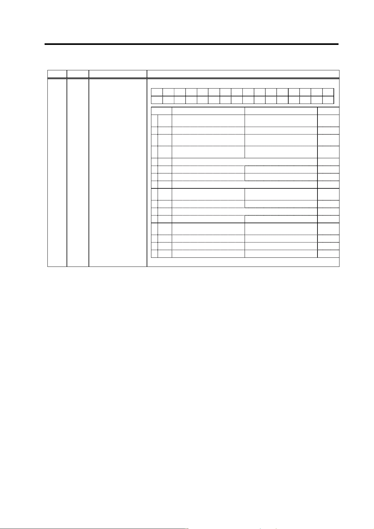
<For MDS-C1-SPM>
FEDCBA98765 4 3 2 10
XFzs
pl80 sdt2 vfbs orm tdn plg2 pftm alty
bit Meaning when set to 0 Meaning when set to 1 Standard
0alty
Deceleration stop during special
alarm invalid
Deceleration stop during special
alarm valid
0
1 0
2 pftm
Encoder feedback serial
communication invalid
Encoder feedback serial
communication valid
0
3plg2
Semi-closed pulse output signal ×2
invalid
Semi-closed pulse output signal ×2
valid
0
SP038 SFNC6* Spindle function 6
4 tdn This is used by Mitsubishi. Set to "0" unless particularly designated. 0
5 0
6 orm Orientation start memo invalid Orientation start memo valid 0
7 vfbs This is used by Mitsubishi. Set to "0" unless particularly designated. 0
8 sdt2 (Follows SP038/bitC setting)
Set output 2 to 2nd speed detection
output
0
9 pl80 MHE90K detector's 180 wave PLG 180 wave PLG other than MHE90K 0
A 0
B 0
CXFzs
Set output 2 to MP scale low (L)
speed mode
Set output 2 to zero speed output 0
D 0
E 0
F 0
(Note) Set 0 if there is no particular explanation for the bit.
Parameters with an asterisk * in the abbreviation, such as OSP*, are validated with the NC power turned ON again.
3. Setup
3 - 81
No. Abbr. Parameter name Details
Setting range
(Unit)
Standard
setting
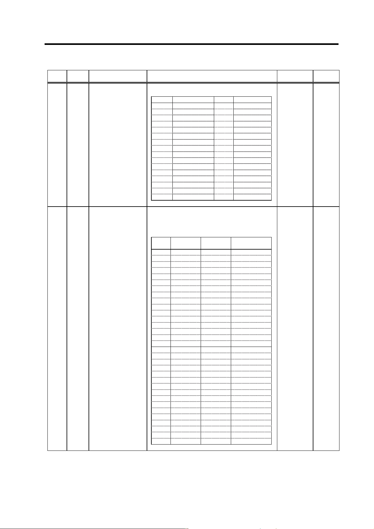
Set the spindle drive unit's capacity type.
(HEX setting)
Setting Unit capacity Setting Unit capacity
0000 --- 0010 MDS-B-SP-550
0001 MDS-C1-SP-075 0011 ---
0002 MDS-C1-SP-15 0012 ---
0003 MDS-C1-SP-22 0013 ---
0004 MDS-C1-SP-37 0014 ---
0005 MDS-C1-SP-55 0015 ---
SP039 ATYP* Drive unit type 0006 MDS-C1-SP-75 0016 --- 0000 to FFFF 0000
0007 MDS-C1-SP-110 0017 ---
0008 MDS-C1-SP-150 0018 ---
0009 MDS-C1-SP-185 0019 ---
000A MDS-C1-SP-220 001A ---
000B MDS-C1-SP-260 001B ---
000C MDS-C1-SP-300 001C ---
000D MDS-B-SP-370 001D ---
000E MDS-B-SP-450 001E ---
000F MDS-C1-SP-04 001F ---
This parameter is valid when SP034 (SFNC2)/bit0 is set
to "0". (Old type of motor)
Set the appropriate motor number from the standard
motors listed below.
(HEX setting)
Setting Motor name
Maximum
speed
Corresponding
drive unit
0000 --- --- ---
0001 SJ-2.2A 10000 r/min MDS-C1-SP-22
0002 SJ-3.7A 10000 r/min MDS-C1-SP-37
0003 SJ-5.5A 8000 r/min MDS-C1-SP-55
0004 SJ-7.5A 8000 r/min MDS-C1-SP-75
0005 SJ-11A 6000 r/min MDS-C1-SP-110
0006 SJ-15A 6000 r/min MDS-C1-SP-150
0007 SJ-18.5A 6000 r/min MDS-C1-SP-185
0008 SJ-22A 4500 r/min MDS-C1-SP-220
0009 SJ-26A 4500 r/min MDS-C1-SP-260
SP040 MTYP* Motor type 000A SJ-30A 4500 r/min MDS-C1-SP-300 0000 to FFFF 0000
000B --- --- ---
000C --- --- ---
000D --- --- ---
000E --- --- ---
000F --- --- ---
0010 --- --- ---
0011 SJ-N0.75A 10000 r/min MDS-C1-SP-075
0012 SJ-N1.5A 10000 r/min MDS-C1-SP-15
0013 SJ-N2.2A 10000 r/min MDS-C1-SP-22
0014 SJ-N3.7A 10000 r/min MDS-C1-SP-37
0015 SJ-N5.5A 8000 r/min MDS-C1-SP-55
0016 SJ-N7.5A 8000 r/min MDS-C1-SP-75
0017 --- --- ---
0018 --- --- ---
0019 --- --- ---
001A --- --- ---
001B --- --- ---
001C --- --- ---
001D --- --- ---
001E --- --- ---
001F --- --- ---
Parameters with an asterisk * in the abbreviation, such as OSP*, are validated with the NC power turned ON again.
3. Setup
3 - 82
No. Abbr. Parameter name Details
Setting range
(Unit)
Standard
setting
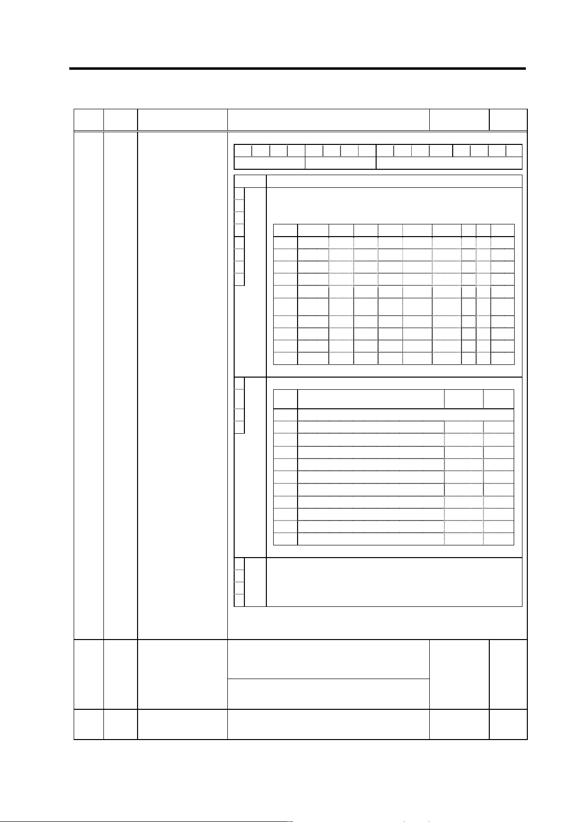
F E D C B A 9 8 7 6 5 4 3 2 1 0
amp rtyp ptyp
bit Explanation
0
1
2
When the CN4 connector of the drive unit and the power supply are
connected, setting below is necessary.
To validate the external emergency stop function, add 40h.
3
Setting 0x 1x 2x 3x 4x 5x 6x 7x 8x
4
x0 Not used CV-300
5
x1 CV-110 CR-10
6
x2 CV-220 CR-15
7
ptyp
x3 CR-22
x4 CV-37 CR-37
x5 CV-150
MDS-B-
CVE-450
MDS-B-
CVE-550
x6 CV-55 CV-260 CR-55
x7 CV-370
x8 CV-75 CR-75
x9 CV-185 CR-90
SP041 PTYP* Power supply type
8
Set the regenerative resistor type when MDS-A-CR is used.
9 Setting Regenerative resistor model name
Resistance
value
Capacity
A0
MDS-C1-CV (Setting when using power supply regeneration)
B
rtyp
1
GZG200W260HMJ (Note)
26Ω
80W
2
GZG300W130HMJ×2
26Ω
150W
3
MR-RB30
13Ω
300W
4
MR-RB50
13Ω
500W
5
GZG200W200HMJ×3
6.7Ω
350W
6
GZG300W200HMJ×3
6.7Ω
500W
7
R-UNIT-1
30Ω
700W
8
R-UNIT-2
15Ω
700W
9
R-UNIT-3
15Ω
2100W
A~F
No setting
C
D
E
F
amp
Always set to "0".
(Note) When MDS-B-SP-370, 450 or 550 is used, set "0" even if power
regeneration type is applied.
<For MDS-C1-SP/SPH/SPM>
This parameter is used to set the C-axis detector range.
Set "0" for this parameter.
"2" is used by Mitsubishi for testing.
SP042 CRNG* C-axis detector range
<For MDS-C1-SPX/SPHX>
Set the number of pulses for the spindle end PLG.
"4" = 128, "5" = 256, "6" = 512, "8" = 180
0 to 8 0
SP043 TRNG*
Synchronous tapping,
spindle synchronous
detector range
This parameter is used to set the synchronous tapping or
spindle synchronous detector range.
Set "0" for this parameter.
0 to 7 0
Parameters with an asterisk * in the abbreviation, such as OSP*, are validated with the NC power turned ON again.