bnp-b2365(eng)b.pdf - 第182页
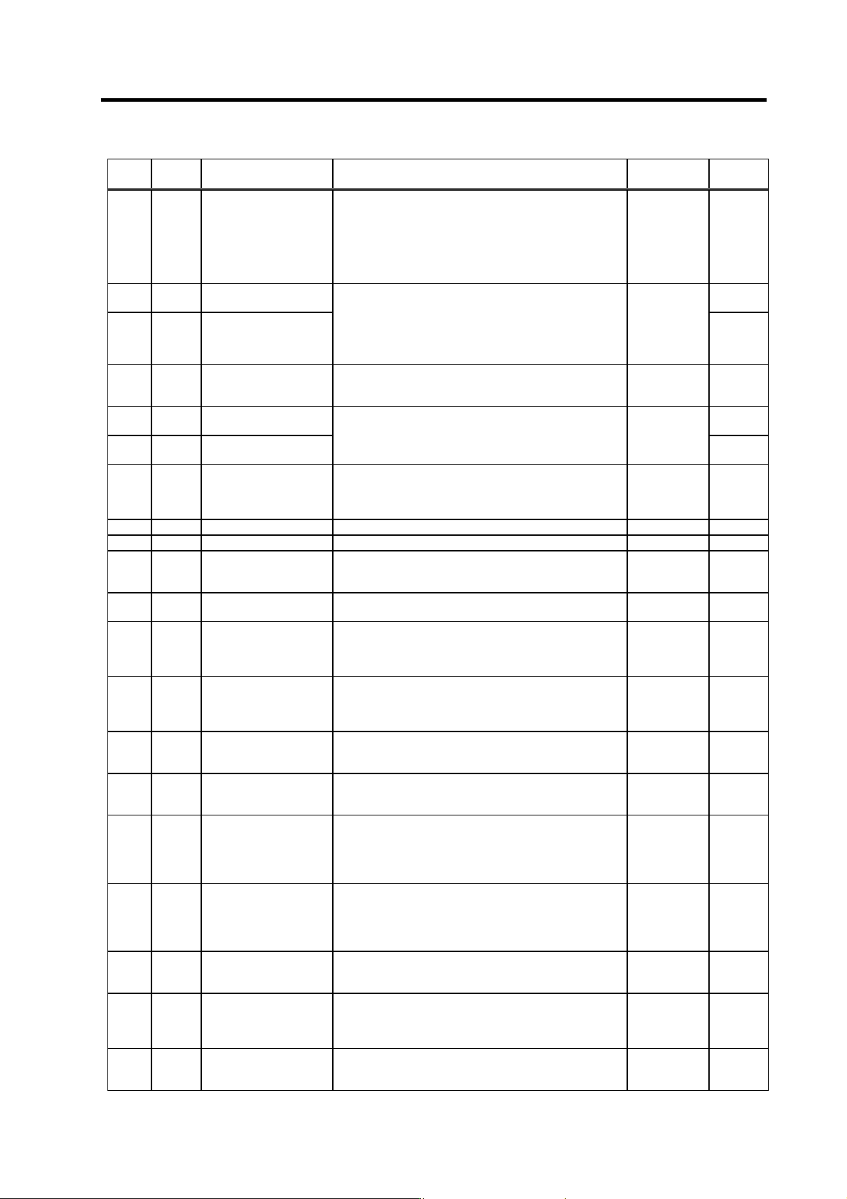
3. Setup 3 - 95 No. Abbr. Parameter name Details Setting rang e (Unit) Standard setting SP170 VGUD* Speed loop gain delay advance item for increased spindle holding force Set the speed loop gain delay advance item for wh…
3. Setup
3 - 94
No. Abbr. Parameter name Details
Setting range
(Unit)
Standard
setting
SP150 CPDT
C-axis control zero point
return deceleration point
This parameter is valid when SP129 (SPECC)/bitE is set
to "0".
Set the deceleration rate where the machine starts to
decelerate when it returns to the target stop point during
C-axis zero point return.
When the machine tends to overshoot at the stop point,
set the smaller value.
1 to 10000 1
SP151 CPSTL
C-axis zero point return
shift amount (low byte)
0000
SP152 CPSTH
C-axis zero point return
shift amount (high byte)
This parameter is valid when SPECC (SP129)/bitE is set
to "0".
Set the C-axis zero point position.
(HEX setting)
00000000 to
FFFFFFFF
Only for SPX
00000000 to
00057E3F
(1/1000 deg)
0000
SP153 CINP
C-axis control in-position
width
Set the position error range for outputting the in-position
signal during C-axis control.
(HEX setting)
0000 to FFFF
(1/1000 deg)
03E8
SP154 CODRL*
Excessive error width on
C-axis control (low byte)
D4C0
SP155
CODRH*
Excessive error width on
C-axis control (high byte)
Set the excessive error width on the C-axis control.
(HEX setting)
00000000 to
FFFFFFFF
(1/1000 deg)
0001
SP156 OVSH
C-axis control overshoot
compensation
Set this to prevent overshooting when shifting from
movement to stopping with C-axis control.
(Set this referring to the load meter display when
overshooting occurred.)
0 to 1000
(0.1%)
0
SP157 Not used. Set to "0". 0 0
SP158 Not used. Set to "0". 0 0
SP159 CPY0
C-axis non-cutting
control variable
excitation ratio
Set the minimum value of variable excitation ratio for
non-cutting control on the C-axis.
0 to 100 (%) 50
SP160 CPY1
C-axis cutting control
variable excitation ratio
Set the minimum variable excitation ratio for cutting
control on the C-axis.
0 to 100 (%) 100
SP161 IQGC0*
Current loop gain
magnification 1 for
non-cutting control on
C-axis
Set the magnification of current loop gain (torque
component) for C-axis non-cutting control.
1 to 1000 (%) 100
SP162 IDGC0*
Current loop gain
magnification 2 for
non-cutting control on
C-axis
Set the magnification of current loop gain (excitation
component) for C-axis non-cutting control.
1 to 1000 (%) 100
SP163 IQGC1*
Current loop gain
magnification 1 for
cutting control on C-axis
Set the magnification of current loop gain (torque
component) for C-axis cutting control. 1 to 1000 (%) 100
SP164 IDGC1*
Current loop gain
magnification 2 for
cutting control on C-axis
Set the magnification of current loop gain (excitation
component) for C-axis cutting control. 1 to 1000 (%) 100
SP165 PG2C
C-axis control position
loop gain 2
Set the second position loop gain when high-gain control
is carried out for control of the C-axis.
This parameter is applied to all the operation modes of
C-axis control.
When this function is not used, assign "0".
0 to 999
(rad/s)
0
SP166 PG3C
C-axis control position
loop gain 3
Set the third position loop gain when high-gain control is
carried out for control of the C-axis.
This parameter is applied to all the operation modes of
C-axis control.
When this function is not used, assign "0".
0 to 999
(rad/s)
0
SP167 PGU*
Position loop gain for
increased spindle
holding force
Set the position loop gain for when the disturbance
observer is valid.
0 to 999
(rad/s)
15
SP168 VGUP*
Speed loop gain
proportional item for
increased spindle
holding force
Set the speed loop gain proportional item for when the
disturbance observer is valid.
0 to 5000 63
SP169 VGUI*
Speed loop gain integral
item for increased
spindle holding force
Set the speed loop gain integral item for when the
disturbance observer is valid. 0 to 5000 60
Parameters with an asterisk * in the abbreviation, such as OSP*, are validated with the NC power turned ON again.
3. Setup
3 - 95
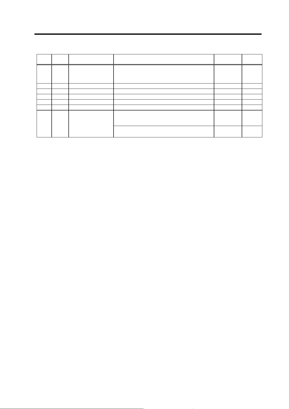
No. Abbr. Parameter name Details
Setting range
(Unit)
Standard
setting
SP170 VGUD*
Speed loop gain delay
advance item for
increased spindle
holding force
Set the speed loop gain delay advance item for when the
disturbance observer is valid.
0 to 5000 15
SP171 Not used. Set "0". 0 0
SP172 Not used. Set "0". 0 0
SP173 Not used. Set "0". 0 0
SP174 Not used. Set "0". 0 0
SP175 Not used. Set "0". 0 0
<For MDS-C1-SP/SPH/SPX/SPHX>
Set the time until gate OFF after zero speed (ZS) is
detected at speed control.
0 to 1000
(10ms)
0
SP176 ZGOF
Gate OFF delay time
after zero speed
detection
< For MDS-C1-SPM>
Not used. Set "0".
0 0
Parameters with an asterisk * in the abbreviation, such as OSP*, are validated with the NC power turned ON again.
3. Setup
3 - 96
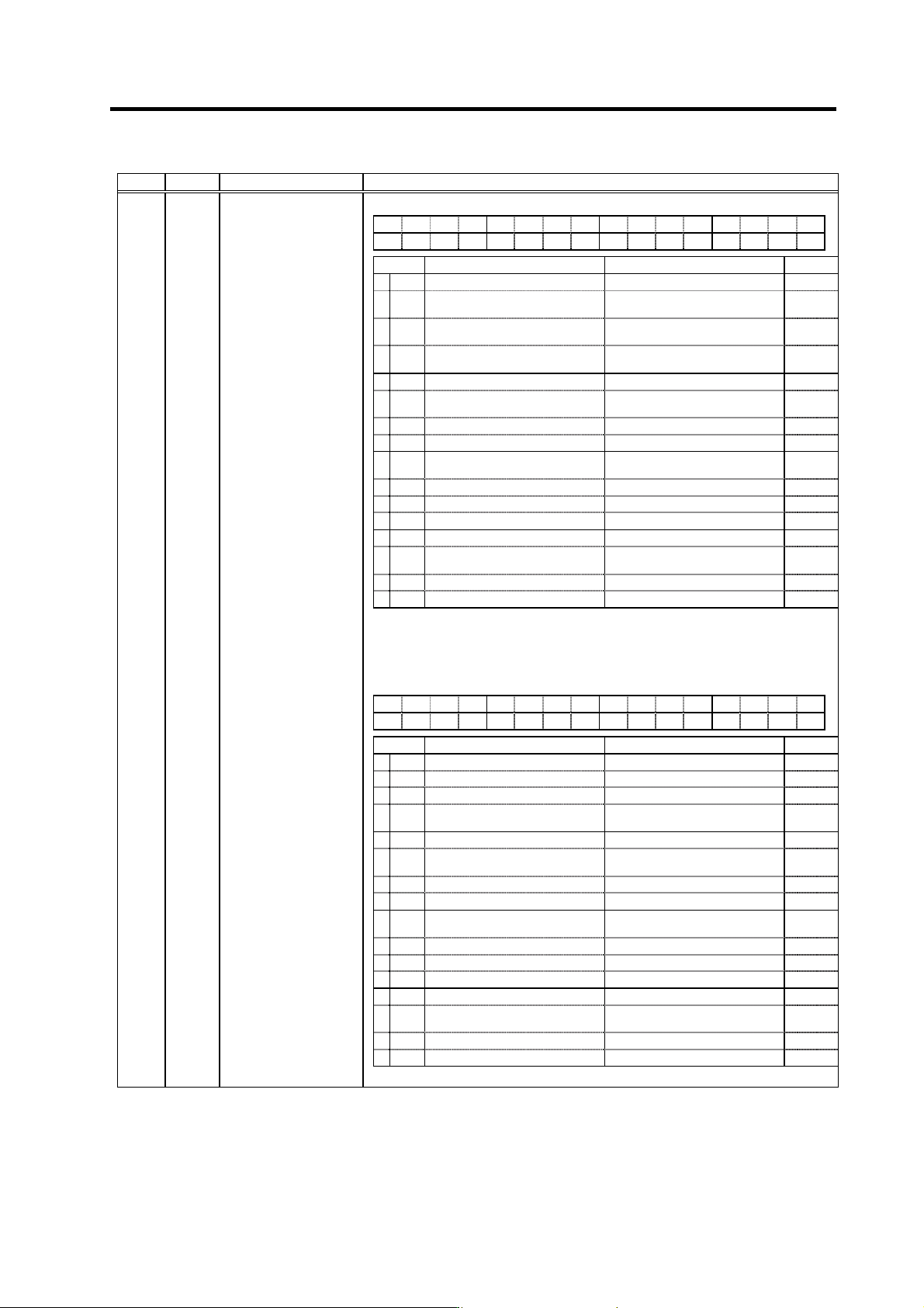
No. Abbr. Parameter name Details
<For MDS-C1-SP/SPH/SPX/SPHX>
FEDCBA98765 4 3 2 10
odx8 phos fdir pyfx rtrn adin fclx
bit Meaning when set to 0 Meaning when set to 1 Standard
0 fclx Closed loop Semi-closed loop 0
1 adin
Interpolation A/D compensation
invalid
Interpolation A/D compensation
valid
0
2rtrn
Position monitor during ready OFF
invalid
Position monitor during ready OFF
valid
0
3 pyfx Normal excitation
Position loop excitation fixed
(strong)
0
4 0
5fdir
Position detector direc-
tion (positive direction)
Position detector direc-
tion (negative direction)
0
6 0
7 0
8 phos
High-gain servo synchronous
compensation invalid
High-gain servo synchronous
compensation valid
0
9 0
A 0
B 0
C 0
D odx8
Excessive error detection width
normal
Magnification of excessive error
detection width × 8 times valid
0
E 0
F 0
SP177 SPECS*
Spindle synchronous
specifications
(Note 1) bits 5, D and F are invalid for SPX and SPHX. Set the direction with
SP097.
(Note 2) Set 0 if there is no particular explanation for the bit.
<For MDS-C1-SPM>
FEDCBA98765 4 3 2 10
odx8 phos fdir
mach
fclx
bit Meaning when set to 0 Meaning when set to 1 Standard
0 fclx Closed loop Semi-closed loop 0
1 0
2 0
3mach
Automatic coil changeover during
spindle synchronization invalid
Automatic coil changeover during
spindle synchronization valid
0
4 0
5fdir
Position detector direction
(positive direction)
Position detector direction
(negative direction)
0
6 0
7 0
8 phos
High-gain servo synchronous
compensation invalid
High-gain servo synchronous
compensation valid
1
9 0
A 0
B 0
C 0
D odx8
Excessive error detection width
normal
Magnification of excessive error
detection width × 8 times valid
0
E 0
F 0
(Note) Set 0 if there is no particular explanation for the bit.
Parameters with an asterisk * in the abbreviation, such as OSP*, are validated with the NC power turned ON again.