bnp-b2365(eng)b.pdf - 第183页
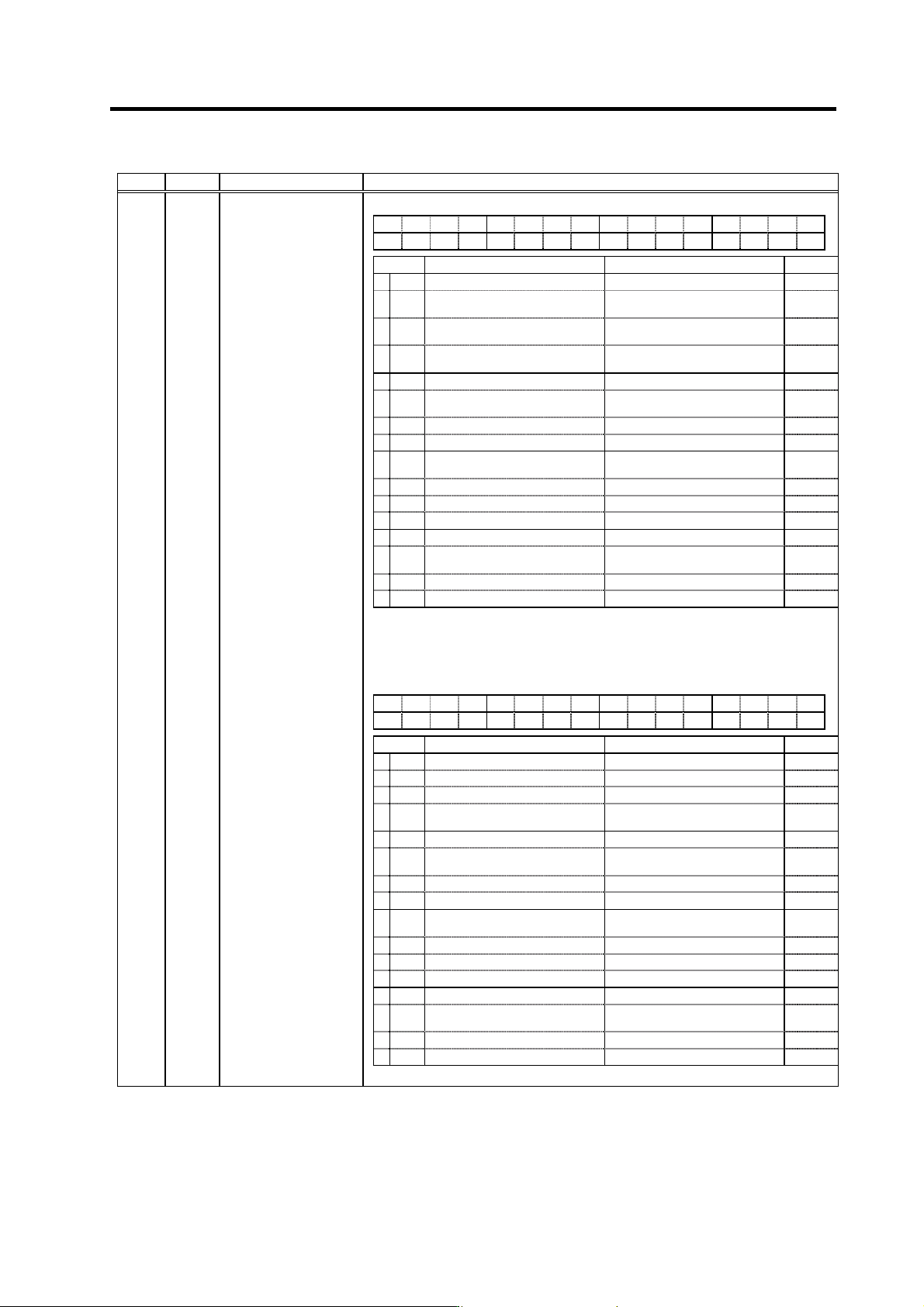
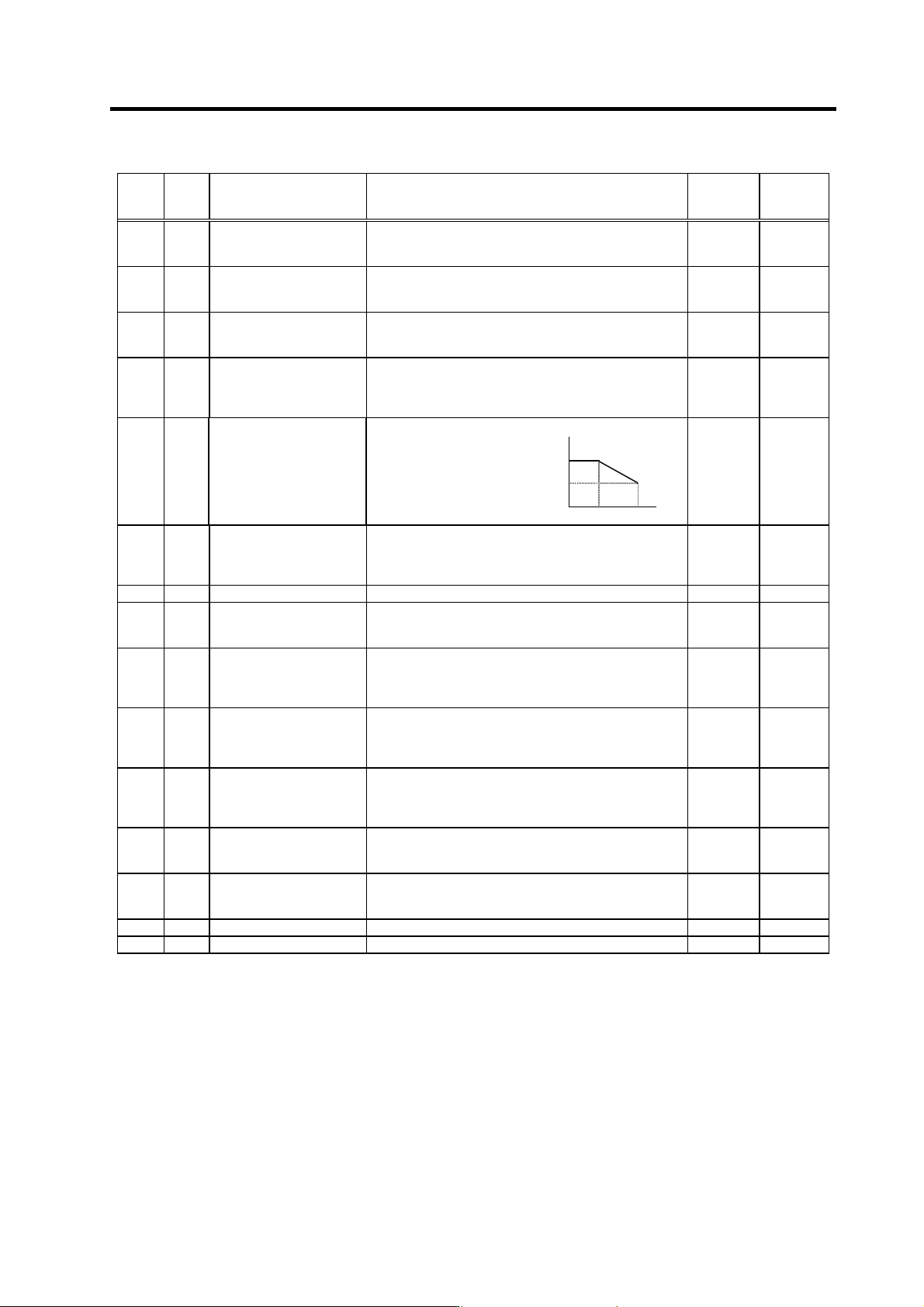
3. Setup 3 - 96 No. Abbr. Parameter name Details <For MDS-C1-SP/SPH/SPX/SPHX> F E D C B A 98765 4 3 2 10 odx8 phos fdir pyfx rtrn adin fclx bit Meaning when set to 0 Meaning when set to 1 Standard 0 f clx Closed lo…
3. Setup
3 - 95
No. Abbr. Parameter name Details
Setting range
(Unit)
Standard
setting
SP170 VGUD*
Speed loop gain delay
advance item for
increased spindle
holding force
Set the speed loop gain delay advance item for when the
disturbance observer is valid.
0 to 5000 15
SP171 Not used. Set "0". 0 0
SP172 Not used. Set "0". 0 0
SP173 Not used. Set "0". 0 0
SP174 Not used. Set "0". 0 0
SP175 Not used. Set "0". 0 0
<For MDS-C1-SP/SPH/SPX/SPHX>
Set the time until gate OFF after zero speed (ZS) is
detected at speed control.
0 to 1000
(10ms)
0
SP176 ZGOF
Gate OFF delay time
after zero speed
detection
< For MDS-C1-SPM>
Not used. Set "0".
0 0
Parameters with an asterisk * in the abbreviation, such as OSP*, are validated with the NC power turned ON again.
3. Setup
3 - 96
No. Abbr. Parameter name Details
<For MDS-C1-SP/SPH/SPX/SPHX>
FEDCBA98765 4 3 2 10
odx8 phos fdir pyfx rtrn adin fclx
bit Meaning when set to 0 Meaning when set to 1 Standard
0 fclx Closed loop Semi-closed loop 0
1 adin
Interpolation A/D compensation
invalid
Interpolation A/D compensation
valid
0
2rtrn
Position monitor during ready OFF
invalid
Position monitor during ready OFF
valid
0
3 pyfx Normal excitation
Position loop excitation fixed
(strong)
0
4 0
5fdir
Position detector direc-
tion (positive direction)
Position detector direc-
tion (negative direction)
0
6 0
7 0
8 phos
High-gain servo synchronous
compensation invalid
High-gain servo synchronous
compensation valid
0
9 0
A 0
B 0
C 0
D odx8
Excessive error detection width
normal
Magnification of excessive error
detection width × 8 times valid
0
E 0
F 0
SP177 SPECS*
Spindle synchronous
specifications
(Note 1) bits 5, D and F are invalid for SPX and SPHX. Set the direction with
SP097.
(Note 2) Set 0 if there is no particular explanation for the bit.
<For MDS-C1-SPM>
FEDCBA98765 4 3 2 10
odx8 phos fdir
mach
fclx
bit Meaning when set to 0 Meaning when set to 1 Standard
0 fclx Closed loop Semi-closed loop 0
1 0
2 0
3mach
Automatic coil changeover during
spindle synchronization invalid
Automatic coil changeover during
spindle synchronization valid
0
4 0
5fdir
Position detector direction
(positive direction)
Position detector direction
(negative direction)
0
6 0
7 0
8 phos
High-gain servo synchronous
compensation invalid
High-gain servo synchronous
compensation valid
1
9 0
A 0
B 0
C 0
D odx8
Excessive error detection width
normal
Magnification of excessive error
detection width × 8 times valid
0
E 0
F 0
(Note) Set 0 if there is no particular explanation for the bit.
Parameters with an asterisk * in the abbreviation, such as OSP*, are validated with the NC power turned ON again.
3. Setup
3 - 97
No. Abbr. Parameter name Details
Setting
range
(Unit)
Standard
setting
SP178 VGSP*
Spindle synchronous
control speed loop gain
proportional term
Set the speed loop proportional gain in spindle
synchronous control mode. 0 to 1000 63
SP179 VGSI*
Spindle synchronous
control speed loop gain
integral term
Set the speed loop integral gain in spindle synchronous
control mode. 0 to 1000 60
SP180 VGSD*
Spindle synchronous
control speed loop gain
delay advance term
Set the speed loop delay advance gain in spindle
synchronous control mode.
When this parameter is set to "0", PI control is applied.
0 to 1000 15
SP181 VCGS*
Spindle synchronous
control
Target value of variable
speed loop proportional gain
Set the magnification of speed loop proportional gain with
respect to SP178 (VGSP) at the maximum speed defined
in SP017 (TSP) in spindle synchronous control mode.
0 to 100 (%) 100
SP178
SP178 X
(SP181/100)
SP182 VCSS*
Spindle synchronous
control
Change starting speed of
variable speed loop
proportional gain
Set the speed when the
speed loop proportional
gain change starts in
the spindle
synchronous control
mode.
0 SP182 SP017
0 to 32767
(r/min)
0
SP183 SYNV
Spindle synchronous
control
Sync matching speed
For changeover from the speed loop to the position loop
in the spindle synchronous control mode, set a speed
command error range for output of the synchronous
speed matching signal.
0 to 1000
(r/min)
20
SP184 Not used. Set "0". 0 0
SP185 SINP
Spindle synchronous
control
In-position width
Set the position error range for output of the in-position
signal in the spindle synchronous control mode.
1 to 2880
(1/16 deg)
16
SP186 SODR*
Spindle synchronous
control
Excessive error width
Set the excessive error width in the spindle synchronous
control mode.
0 to 32767
(pulse)
(1 pulse =
0.088 deg)
32767
SP187 IQGS*
Spindle synchronous
control
Current loop gain
magnification1
Set the magnification of current loop gain (torque
component) in the spindle synchronous control mode. 1 to 1000
(%)
100
SP188 IDGS*
Spindle synchronous
control
Current loop gain
magnification 2
Set the magnification of current loop gain (excitation
component) in the spindle synchronous control mode. 1 to 1000
(%)
10
SP189 PG2S
Spindle synchronous
control
Position loop gain 2
Set the second position loop gain when high-gain control
is carried out in the spindle synchronous control mode.
When this parameter function is not used, set to "0".
0 to 999
(rad/s)
0
SP190 PG3S
Spindle synchronous
control
Position loop gain 3
Set the third position loop gain when high-gain control is
carried out in the spindle synchronous control mode.
When this parameter function is not used, set to "0".
0 to 999
(rad/s)
0
SP191 Not used. Set "0". 0 0
SP192 Not used. Set "0". 0 0
Parameters with an asterisk * in the abbreviation, such as OSP*, are validated with the NC power turned ON again.