bnp-b2365(eng)b.pdf - 第185页
3. Setup 3 - 98 No. Abbr. Parameter name Details <For MDS-C1-SP/SPH/SPX/SPHX> F E D C B A 98765 4 3 2 10 zrtn ptyp od8x phos fdir cdir pyfx rtrn adin fclx bit Meaning when set to 0 Meaning when set to 1 Standard 0 …
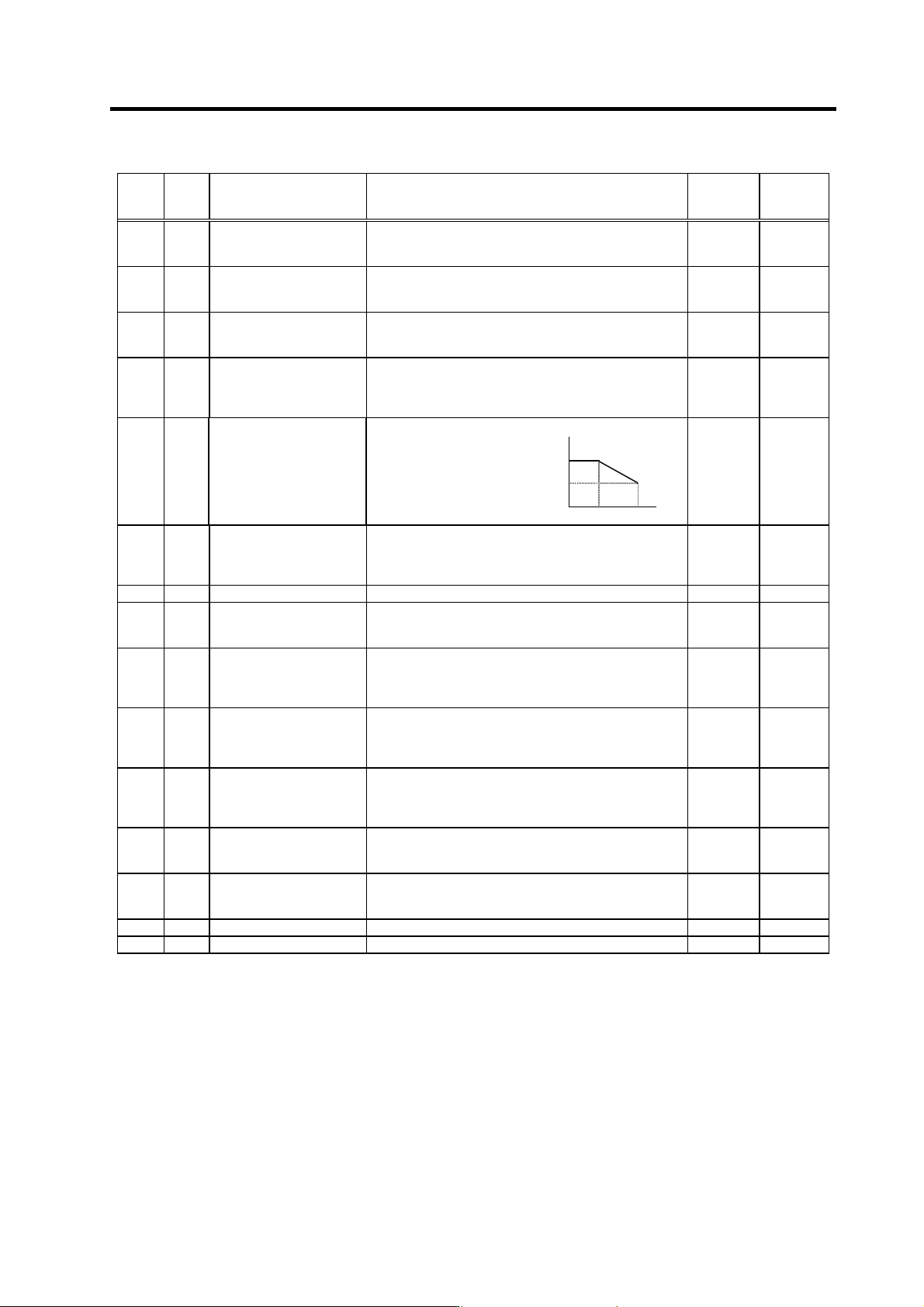
3. Setup
3 - 97
No. Abbr. Parameter name Details
Setting
range
(Unit)
Standard
setting
SP178 VGSP*
Spindle synchronous
control speed loop gain
proportional term
Set the speed loop proportional gain in spindle
synchronous control mode. 0 to 1000 63
SP179 VGSI*
Spindle synchronous
control speed loop gain
integral term
Set the speed loop integral gain in spindle synchronous
control mode. 0 to 1000 60
SP180 VGSD*
Spindle synchronous
control speed loop gain
delay advance term
Set the speed loop delay advance gain in spindle
synchronous control mode.
When this parameter is set to "0", PI control is applied.
0 to 1000 15
SP181 VCGS*
Spindle synchronous
control
Target value of variable
speed loop proportional gain
Set the magnification of speed loop proportional gain with
respect to SP178 (VGSP) at the maximum speed defined
in SP017 (TSP) in spindle synchronous control mode.
0 to 100 (%) 100
SP178
SP178 X
(SP181/100)
SP182 VCSS*
Spindle synchronous
control
Change starting speed of
variable speed loop
proportional gain
Set the speed when the
speed loop proportional
gain change starts in
the spindle
synchronous control
mode.
0 SP182 SP017
0 to 32767
(r/min)
0
SP183 SYNV
Spindle synchronous
control
Sync matching speed
For changeover from the speed loop to the position loop
in the spindle synchronous control mode, set a speed
command error range for output of the synchronous
speed matching signal.
0 to 1000
(r/min)
20
SP184 Not used. Set "0". 0 0
SP185 SINP
Spindle synchronous
control
In-position width
Set the position error range for output of the in-position
signal in the spindle synchronous control mode.
1 to 2880
(1/16 deg)
16
SP186 SODR*
Spindle synchronous
control
Excessive error width
Set the excessive error width in the spindle synchronous
control mode.
0 to 32767
(pulse)
(1 pulse =
0.088 deg)
32767
SP187 IQGS*
Spindle synchronous
control
Current loop gain
magnification1
Set the magnification of current loop gain (torque
component) in the spindle synchronous control mode. 1 to 1000
(%)
100
SP188 IDGS*
Spindle synchronous
control
Current loop gain
magnification 2
Set the magnification of current loop gain (excitation
component) in the spindle synchronous control mode. 1 to 1000
(%)
10
SP189 PG2S
Spindle synchronous
control
Position loop gain 2
Set the second position loop gain when high-gain control
is carried out in the spindle synchronous control mode.
When this parameter function is not used, set to "0".
0 to 999
(rad/s)
0
SP190 PG3S
Spindle synchronous
control
Position loop gain 3
Set the third position loop gain when high-gain control is
carried out in the spindle synchronous control mode.
When this parameter function is not used, set to "0".
0 to 999
(rad/s)
0
SP191 Not used. Set "0". 0 0
SP192 Not used. Set "0". 0 0
Parameters with an asterisk * in the abbreviation, such as OSP*, are validated with the NC power turned ON again.
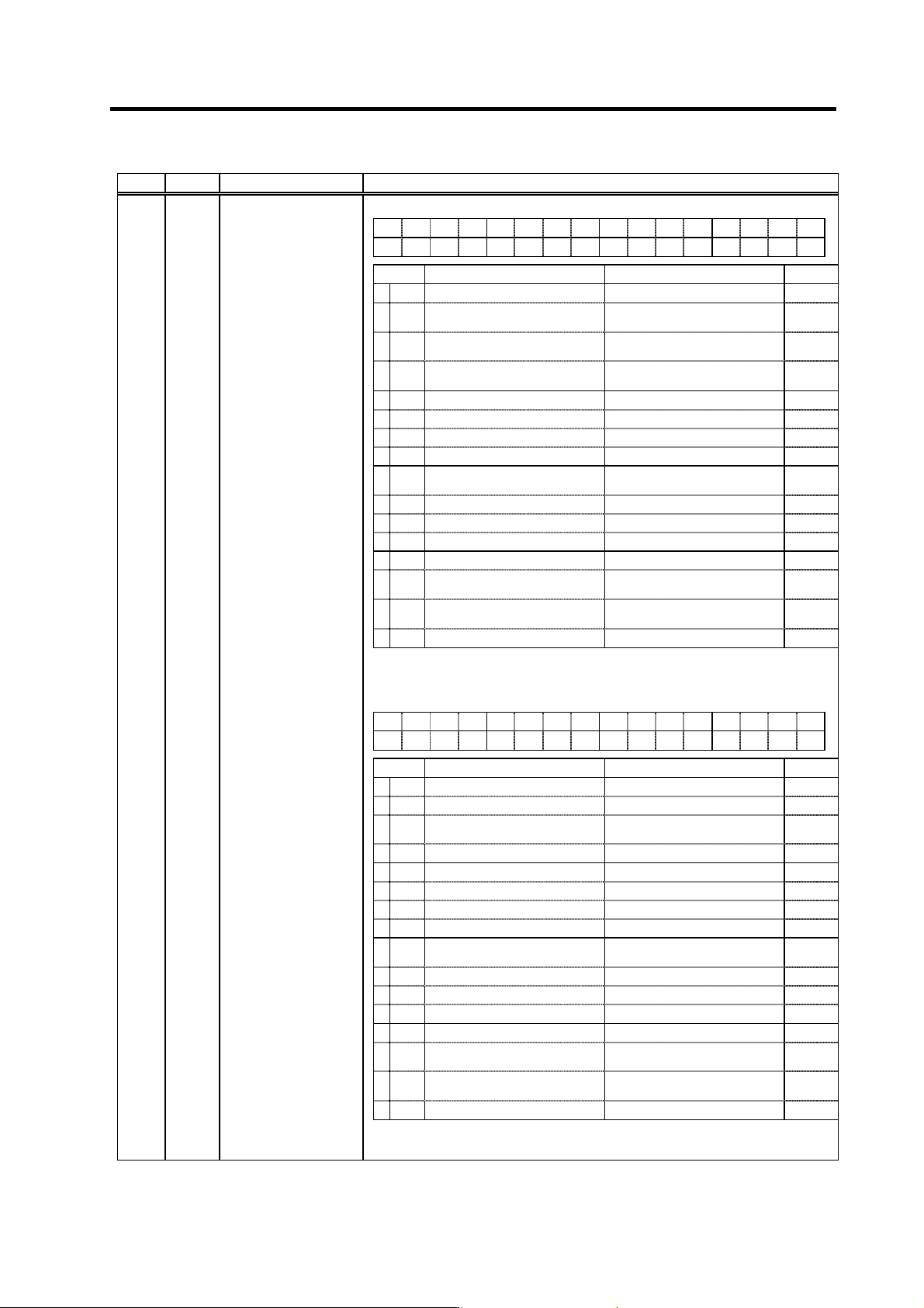
3. Setup
3 - 98
No. Abbr. Parameter name Details
<For MDS-C1-SP/SPH/SPX/SPHX>
FEDCBA98765 4 3 2 10
zrtn ptyp od8x phos fdir cdir pyfx rtrn adin fclx
bit Meaning when set to 0 Meaning when set to 1 Standard
0 fclx Closed loop Semi-closed loop (Gear 1 : 1 only) 0
1 adin
Interpolation A/D compensation
invalid
Interpolation A/D compensation
valid
0
2rtrn
Position monitor during ready OFF
invalid
Position monitor during ready OFF
valid
0
3 pyfx Normal excitation
Position loop excitation fixed
(strong)
0
4 cdir Command polarity (+) Command polarity (–) 0
5 fdir Position detector polarity (+) Position detector polarity (–) 0
6 0
7 0
8 phos
High-gain servo synchronous
compensation invalid
High-gain servo synchronous
compensation valid
1
9 0
A 0
B 0
C 0
D od8x
Magnification of excessive error
width × 8 times invalid
Magnification of excessive error
width × 8 times valid
0
Eptyp
Position control switch type: After
zero point return
Position control switch type: After
deceleration stop
0
F zrtn Zero point return direction: CCW Zero point return direction: CW 0
(Note) Set 0 if there is no particular explanation for the bit.
SP193 SPECT*
Synchronized tapping
specifications
<For MDS-C1-SPM>
FEDCBA98765 4 3 2 10
zrtn ptyp od8x phos fdir cdir rtrn fclx
bit Meaning when set to 0 Meaning when set to 1 Standard
0 fclx Closed loop Semi-closed loop (Gear 1 : 1 only) 0
1 0
2rtrn
Position monitor during ready OFF
invalid
Position monitor during ready OFF
valid
0
3pyfx 0
4 cdir Command polarity (+) Command polarity (–) 0
5 fdir Position detector polarity (+) Position detector polarity (–) 0
6 0
7 0
8 phos
High-gain servo synchronous
compensation invalid
High-gain servo synchronous
compensation valid
1
9 0
A 0
B 0
C 0
D od8x
Magnification of excessive error
width × 8 times invalid
Magnification of excessive error
width × 8 times valid
0
Eptyp
Position control switch type: After
zero point return
Position control switch type: After
deceleration stop
0
F zrtn Zero point return direction: CCW Zero point return direction: CW 0
(Note) Set 0 if there is no particular explanation for the bit.
Parameters with an asterisk * in the abbreviation, such as OSP*, are validated with the NC power turned ON again.
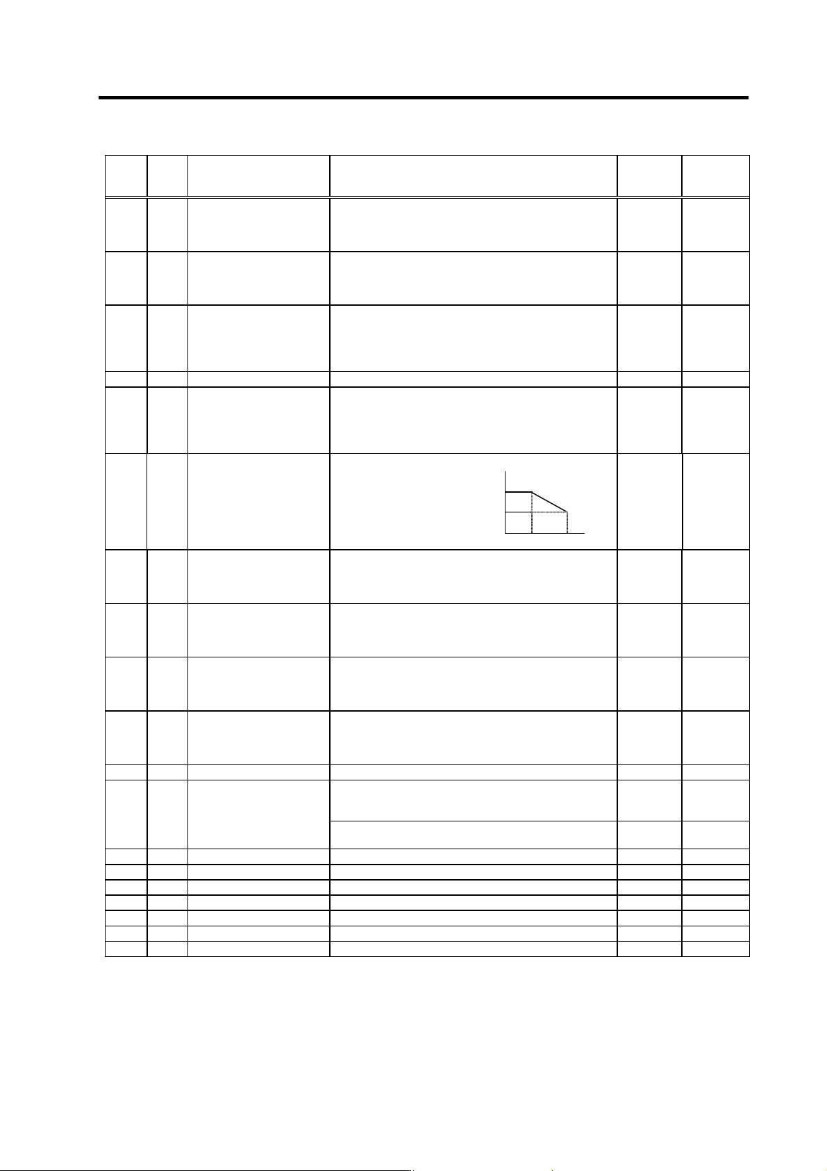
3. Setup
3 - 99
No. Abbr. Parameter name Details
Setting
range
(Unit)
Standard
setting
SP194 VGTP*
Synchronized tapping
control
speed loop gain
proportional term
Set the speed loop proportional gain in synchronized
tapping control mode.
0 to 1000 63
SP195 VGTI*
Synchronized tapping
control
speed loop gain integral
term
Set the speed loop integral gain in synchronized tapping
control mode.
0 to 1000 60
SP196 VGTD*
Synchronized tapping
control
speed loop gain delay
advance
term
Set the speed loop delay advance gain in synchronized
tapping control mode.
When this parameter is set to "0", PI control is applied.
0 to 1000 15
SP197 Fixed control constant Set by Mitsubishi. Set "0" unless designated in particular. 0 0
SP198 VCGT*
Synchronized tapping
control
target value of variable
speed loop proportional
gain
Set the magnification of speed loop proportional gain with
respect to SP194 (VGTP) at the maximum motor speed
defined in SP017 (TSP) in synchronized tapping control
mode.
0 to 100 (%) 100
SP194
SP194×
(SP198/100)
SP199 VCST*
Synchronized tapping
control
change starting speed of
variable speed loop
proportional gain
Set the speed where
the speed loop
proportional gain
change starts during
synchronized tapping
control.
0 SP199 SP017
0 to 32767
(r/min)
0
SP200 FFCI*
Synchronized tapping
control
acceleration feed forward
gain (gear 1)
Set the acceleration feed forward gain for selection of
gear 000 during synchronized tapping control.
This parameter should be used when an error of relative
position to Z-axis servo is large.
0 to 1000
(%)
0
SP201 FFC2*
Synchronized tapping
control
acceleration feed forward
gain (gear 2)
Set the acceleration feed forward gain for selection of
gear 001 during synchronized tapping control.
0 to 1000
(%)
0
SP202 FFC3*
Synchronized tapping
control
acceleration feed forward
gain (gear 3)
Set the acceleration feed forward gain for selection of
gear 010 during synchronized tapping control.
0 to 1000
(%)
0
SP203 FFC4*
Synchronized tapping
control
acceleration feed forward
gain (gear 4)
Set the acceleration feed forward gain for selection of
gear 011 during synchronized tapping control. 0 to 1000
(%)
0
SP204 THOD Fixed control constant Set by Mitsubishi. Set "0" unless designated in particular. 0 0
<For MDS-C1-SPM>
This validates the PLG Z-phase automatic adjustment
function
0 to 1
0 → 1
SP205
ZCHS
PLG Z-phase automatic
adjustment
<For MDS-C1-SP/SPH/SPX/SPHX>
Not used. Set to "0".
0 0
SP206 GCK* Fixed control constant Set by Mitsubishi. Set "0" unless designated in particular. 0 0
SP207 GDL* Fixed control constant Set by Mitsubishi. Set "0" unless designated in particular. 0 0
SP208 W2 Fixed control constant Set by Mitsubishi. Set "0" unless designated in particular. 0 0
SP209 Not used. Set to "0". 0 0
SP210 Not used. Set to "0". 0 0
SP211 Not used. Set to "0". 0 0
SP212 Not used. Set to "0". 0 0
Parameters with an asterisk * in the abbreviation, such as OSP*, are validated with the NC power turned ON again.