bnp-b2365(eng)b.pdf - 第207页
4. Servo Adjustment 4 - 8 During SHG control even if the PGN1 setting value is the same, the actual position loop gain wi ll be higher, so the speed loop must have a sufficie nt response. If the speed loop respon se is l…
4. Servo Adjustment
4 - 7
(2) Setting the position loop gain for spindle synchronous con trol
During spindle synchronous control (synchronous tapping control, etc.), there are three sets of
position loop gain parameters besides the normal control.
No. Abbrev. Parameter name Explanation Setting range
SV049 PGN1sp Position loop gain 1
in spindle
synchronous control
Set 15 as a standard. 1 to 200
(rad/s)
SV050 PGN2sp Position loop gain 2
in spindle
synchronous control
Set 0 as a standard.
(For SHG control)
0 to 999
SV058 SHGCsp SHG control gain in
spindle synchronous
control
Set 0 as a standard.
(For SHG control)
Set the same parameter as the
position loop gain for the spindle
synchronous control.
0 to 1200
CAUTION
Always set the same value for the position loop gain between the spindle and
servo synchronous axes.
(3) SHG control (option function)
If the position loop gain is increased or feed forward control (NC function) is used to shorten the
settling time or increase the precision, the machine system may vibrate easily.
SHG control changes the position loop to a high-gain by stably compensating the servo system
position loop through a delay. This allows the settling time to be reduced and a high precision to be
achieved. (SHG: Smooth High-Gain)
(Feature 1) When the SHG control is set, even if PGN1 is set to the same value as the
conventional gain, the position loop gain will be doubled.
(Feature 2) The SHG control response is smoother than conventional position control during
acceleration/deceleration, so the gain can be increased further with SHG control
compared to the conventional position control.
(Feature 3) With SHG control, a high gain is achieved so a high precision can be obtained during
contour control.
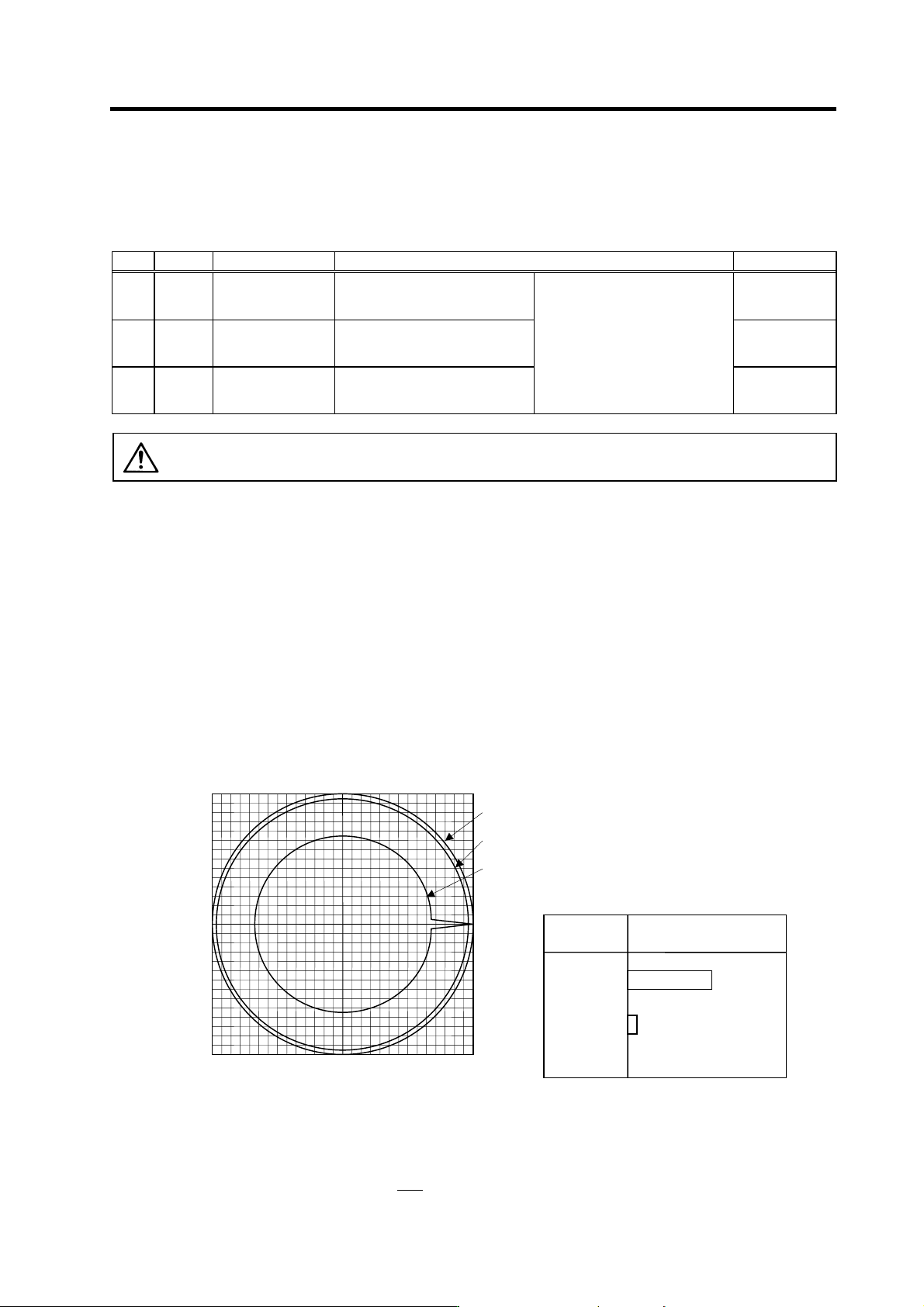
The following drawing shows an example of the improvement in roundness
characteristics with SHG control.
Shape error characteristics
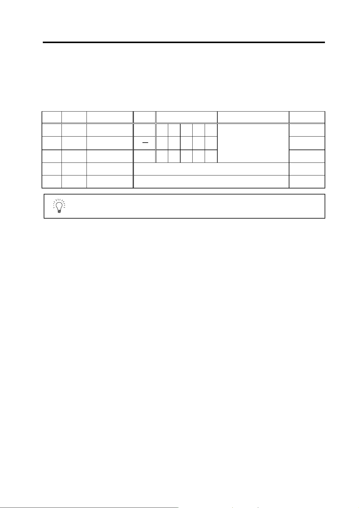
During SHG control, PGN1, PGN2 and SHGC are set with the following ratio.
PGN1 : PGN2 : SHGC = 1 :
8
3
: 6
(F=3000mm/min, ERROR=5.0µm/div)
-50.0 50.00.0
0.0
-50.0
50.0
[1] : Commanded path
[2] : SHG control (PGN1=47)
[3] : Conventional control (PGN1=33)
Conventional
control
SHG control
Control
method
Roundness error (
µ
m)
2.5
22.5
<Effect>
4. Servo Adjustment
4 - 8
During SHG control even if the PGN1 setting value is the same, the actual position loop gain will be
higher, so the speed loop must have a sufficient response. If the speed loop response is low,
vibration or overshooting could occur during acceleration/deceleration in the same manner as
conventional control. If the speed loop gain has been lowered because machine resonance occurs,
lower the position loop gain and adjust.
No.
Abbrev.
Parameter name
Setting
ratio
Setting example Explanation Setting range
SV003
(SV049)
PGN1
(PGN1sp)
Position loop gain 1
1 23 26 33 38 47
1 to 200
SV004
(SV050)
PGN2
(PGN2sp)
Position loop gain 2 8
3
62 70 86 102 125
0 to 999
SV057
(SV058)
SHGC
(SHGCsp)
SHG control gain
6 140 160 187 225 281
Always set with a combination of
these three parameters.
0 to 999
SV008 VIA Speed loop lead
compensation
Set 1900 as a standard for SHG control. 1 to 9999
SV015 FFC Acceleration rate
feed forward gain
Set 100 as a standard for SHG control. 0 to 999
POINT
The SHG control is an optional function. If the option is not set in the CNC, the
alarm 37 (at power ON) or warning E4, Error Parameter No. 104 (2304 for
M60S/E60 Series CNC) will be output.

4. Servo Adjustment
4 - 9
4-3 Characteristics improvement
4-3-1 Optimal adjustment of cycle time
The following items must be adjusted to adjust the cycle time. Refer to the Instruction Manuals provided
with each CNC for the acceleration/deceleration pattern.
[1] Rapid traverse rate (rapid) : This will affect the maximum speed during positioning.
[2] Clamp speed (clamp) : This will affect the maximum speed during cutting.
[3] Acceleration/deceleration time : Set the time to reach the feedrate.
constant (G0t∗, G1t∗)
[4] In-position width (SV024) : This will affect each block's movement command end time.
[5] Position loop gain (SV003) : This will affect each block's movement command settling time.
(1) Adjusting the rapid traverse
To adjust the rapid traverse, the CNC axis specification parameter rapid traverse rate (rapid) and
acceleration/deceleration time constant (G0t∗) are adjusted. The rapid traverse rate is set so that
the motor speed matches the machine specifications in the range below the maximum speed in the
motor specifications. For the acceleration/deceleration time constants, carry out rapid traverse
reciprocation operation, and set so that the maximum current command value at acceleration/
deceleration is within the range shown below. The output torque is limited at areas near the
maximum speed, so monitor the current FB waveform during acceleration/deceleration and adjust
so that the torque is within the specified range.
If the drive unit's input voltage is less than the rated voltage, the torque will easily become
insufficient, and excessive errors will occur easily during acceleration/deceleration.
(2) Adjusting the cutting feed
To adjust the cutting rate, the NC axis specification parameter clamp speed (clamp) and
acceleration/deceleration time constant (G1t∗) are adjusted. The in-position width at this time must
be set to the same value as actual cutting.
• Determining the clamp rate and adjusting the acceleration/deceleration time constant
(Features) The maximum cutting rate (clamp speed) can be determined freely.
(Adjustment) Carry out cutting feed reciprocation operation with no dwell at the maximum
cutting rate and adjust the acceleration/deceleration time constant so that the
maximum current command value during acceleration/deceleration is within the
range shown below.
• Setting the step acceleration/deceleration and adjusting the clamp speed
(Features) The acceleration/deceleration time constant is determined with the position loop
in the servo, so the acceleration/deceleration F∆T can be reduced.
(Adjustment) Set 1 (step) for the acceleration/deceleration time constant and carry out cutting
feed reciprocation operation with no dwell. Adjust the cutting feed rate so that the
maximum current command value during acceleration/deceleration is within the
range shown below, and then set the value in the clamp speed.
Maximum current command value when adjusting acceleration/deceleration time constant
Motor model
Max. current
command value
Motor model
Max. current
command value
Motor model
Max. current
command value
HC52 Within 388% HA053N Within 240% HA40N Within 400%
HC102 Within 340% HA13N Within 240% HA80N Within 365%
HC152 Within 380% HA23N Within 230% HA100N Within 260%
HC202 Within 275% HA33N Within 230% HA200N Within 225%
HC352 Within 251% HA300N Within 200%
HC452 Within 189% HA-LF11K2 Within 215% HA700N Within 205%
HC702 Within 221% HA-LF15K2 Within 240% HA900N Within 220%
HC902 Within 228%
HC452* Within 242% HA43N Within 295%
HC53 Within 264% HC702* Within 248% HA83N Within 275%
HC103 Within 257% HC902* Within 228% HA103N Within 245%
HC153 Within 266% HA203N Within 210%
HC203 Within 257% HC353* Within 242% HA303N Within 180%
HC353 Within 230% HC453* Within 248% HA703N Within 180%
HC453 Within 177% HC703* Within 228%
HC703 Within 189%
(Note) The motor indicated with an asterisk indicates the combination with the S-type drive unit.