bnp-b2365(eng)b.pdf - 第209页
4. Servo Adjustment 4 - 10 (3) Adjusting the in-position width Because there is a resp onse delay in the servomotor drive due to position loop control, a "settling time" is also required for the motor to actual…

4. Servo Adjustment
4 - 9
4-3 Characteristics improvement
4-3-1 Optimal adjustment of cycle time
The following items must be adjusted to adjust the cycle time. Refer to the Instruction Manuals provided
with each CNC for the acceleration/deceleration pattern.
[1] Rapid traverse rate (rapid) : This will affect the maximum speed during positioning.
[2] Clamp speed (clamp) : This will affect the maximum speed during cutting.
[3] Acceleration/deceleration time : Set the time to reach the feedrate.
constant (G0t∗, G1t∗)
[4] In-position width (SV024) : This will affect each block's movement command end time.
[5] Position loop gain (SV003) : This will affect each block's movement command settling time.
(1) Adjusting the rapid traverse
To adjust the rapid traverse, the CNC axis specification parameter rapid traverse rate (rapid) and
acceleration/deceleration time constant (G0t∗) are adjusted. The rapid traverse rate is set so that
the motor speed matches the machine specifications in the range below the maximum speed in the
motor specifications. For the acceleration/deceleration time constants, carry out rapid traverse
reciprocation operation, and set so that the maximum current command value at acceleration/
deceleration is within the range shown below. The output torque is limited at areas near the
maximum speed, so monitor the current FB waveform during acceleration/deceleration and adjust
so that the torque is within the specified range.
If the drive unit's input voltage is less than the rated voltage, the torque will easily become
insufficient, and excessive errors will occur easily during acceleration/deceleration.
(2) Adjusting the cutting feed
To adjust the cutting rate, the NC axis specification parameter clamp speed (clamp) and
acceleration/deceleration time constant (G1t∗) are adjusted. The in-position width at this time must
be set to the same value as actual cutting.
• Determining the clamp rate and adjusting the acceleration/deceleration time constant
(Features) The maximum cutting rate (clamp speed) can be determined freely.
(Adjustment) Carry out cutting feed reciprocation operation with no dwell at the maximum
cutting rate and adjust the acceleration/deceleration time constant so that the
maximum current command value during acceleration/deceleration is within the
range shown below.
• Setting the step acceleration/deceleration and adjusting the clamp speed
(Features) The acceleration/deceleration time constant is determined with the position loop
in the servo, so the acceleration/deceleration F∆T can be reduced.
(Adjustment) Set 1 (step) for the acceleration/deceleration time constant and carry out cutting
feed reciprocation operation with no dwell. Adjust the cutting feed rate so that the
maximum current command value during acceleration/deceleration is within the
range shown below, and then set the value in the clamp speed.
Maximum current command value when adjusting acceleration/deceleration time constant
Motor model
Max. current
command value
Motor model
Max. current
command value
Motor model
Max. current
command value
HC52 Within 388% HA053N Within 240% HA40N Within 400%
HC102 Within 340% HA13N Within 240% HA80N Within 365%
HC152 Within 380% HA23N Within 230% HA100N Within 260%
HC202 Within 275% HA33N Within 230% HA200N Within 225%
HC352 Within 251% HA300N Within 200%
HC452 Within 189% HA-LF11K2 Within 215% HA700N Within 205%
HC702 Within 221% HA-LF15K2 Within 240% HA900N Within 220%
HC902 Within 228%
HC452* Within 242% HA43N Within 295%
HC53 Within 264% HC702* Within 248% HA83N Within 275%
HC103 Within 257% HC902* Within 228% HA103N Within 245%
HC153 Within 266% HA203N Within 210%
HC203 Within 257% HC353* Within 242% HA303N Within 180%
HC353 Within 230% HC453* Within 248% HA703N Within 180%
HC453 Within 177% HC703* Within 228%
HC703 Within 189%
(Note) The motor indicated with an asterisk indicates the combination with the S-type drive unit.
4. Servo Adjustment
4 - 10
(3) Adjusting the in-position width
Because there is a response delay in the servomotor drive due to position loop control, a "settling
time" is also required for the motor to actually stop after the command speed from the CNC reaches
0.
The movement command in the next block is generally started after it is confirmed that the
machine has entered the "in-position width" range set for the machine.
Set the precision required for the machine as the in-position width. If a high precision is set
needlessly, the cycle time will increase due to a delay in the settling time.
The in-position width is validated with the servo parameter settings, but there may be cases when
it is validated with the NC parameters. Refer to each NC Instruction Manual.
No. Abbrev. Parameter name Explanation Setting range
SV024 INP In-position detection
width
Set the in-position detection width.
Set the accuracy required for the machine.
The lower the setting is, the higher the positioning accuracy gets,
however, the cycle time (setting time) becomes longer. The standard
setting is "50".
0 to 32767
(µm)
POINT
The in-position width setting and confirmation availability depend on the CNC
parameters.
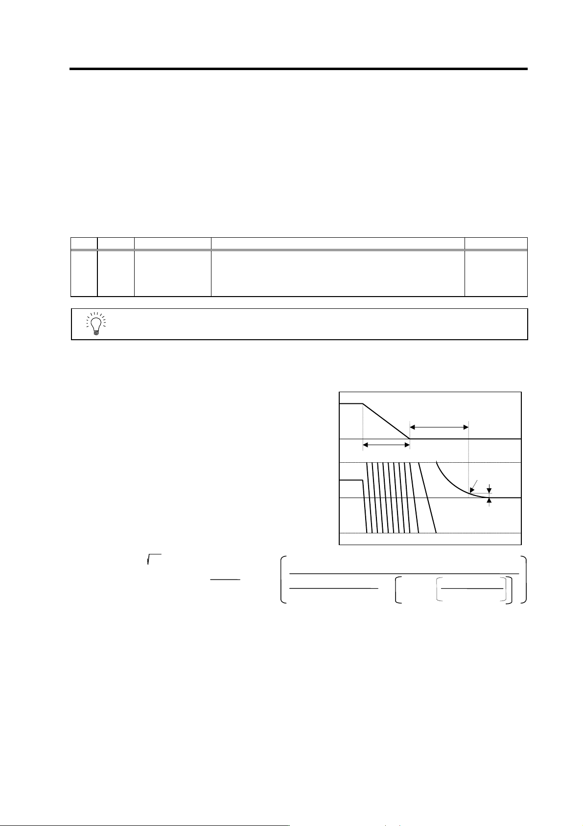
(4) Adjusting the settling tim e
The settling time is the time required for
the position droop to enter the in-position
width after the feed command (F∆T) from
the CNC reaches 0.
The settling time can be shortened by
raising the position loop gain or using
SHG control. However, a sufficient
response (sufficiently large VGN1 setting)
for the speed loop is required to carry out
stable control.
The settling time during normal control
when the CNC is set to linear acceleration/
deceleration can be calculated using the
following equation. During SHG control,
estimate the settling time by multiplying
PGN1 by
2
.
PGN1 : Position loop gain1 (SV003) (rad/s)
F : Rapid traverse rate (mm/min)
G0tL : Rapid traverse linear acceleration/
deceleration time constant (ms)
INP : In-position width (SV024) (µm)
Settling time (ms) = -
•
PGN1
10
3
INP
F × 10
6
60×G0tL×PGN1
2
×
1- exp
PGN1×G0tL
10
3
ln
0
0
F∆T
Position
droop
F
Time
Setting time
In-position
In-position width
G0tL
4. Servo Adjustment
4 - 11
4-3-2 Vibration suppression measures
If vibration (machine resonance) occurs, it can be suppressed by lowering the speed loop gain 1
(VGN1). However, cutting precision and cycle time will be sacrificed. (Refer to "4-2-2 Speed loop
gain".) Thus, try to maintain the VGN1 as high as possible, and suppress the vibration using the
vibration suppression functions.
If the VGN1 is lowered and adjusted because vibration cannot be sufficiently suppressed with the
vibration suppression functions, adjust the entire gain (including the position loop gain) again.
<Examples of vibration occurrence>
• A fine vibration is felt when the machine is touched, or a groaning sound is heard.
• Vibration or noise occurs during rapid traverse.
POINT
Suppress the vibration using the vibration suppression functions, and maintain
the speed loop gain (SV005: VGN1) as high as possible.