bnp-b2365(eng)b.pdf - 第214页
4. Servo Adjustment 4 - 15 4-3-3 Improving the cutting surface precision If the cutting surface precision or ro undness is poor, these can be improved by increa sing the speed loop gain (VGN1, VIA) or by using the distur…
4. Servo Adjustment
4 - 14
(4) Variable speed loop gain control
If vibration occurs when the motor is rotating at a high speed, such during rapid traverse, or if
disturbing noise occurs, the state can be improved by lowering the speed loop gain during
high-speed rotation. The low-speed region speed loop gain used for cutting feed (G1 feed), etc., is
maintained at a high level, so the vibration can be improved without dropping the machining
accuracy.
No. Abbrev. Parameter name Explanation Setting range
SV005 VGN1 Speed loop gain 1 Set the speed loop gain.
Set this according to the load inertia size.
The higher the setting value is, the more accurate the control will be,
however, vibration tends to occur.
If vibration occurs, adjust by lowering by 20 to 30%.
The value should be determined to be 70 to 80% of the value at the
time when the vibration stops.
1 to 999
VGN1
VGN2
VCS VLMT
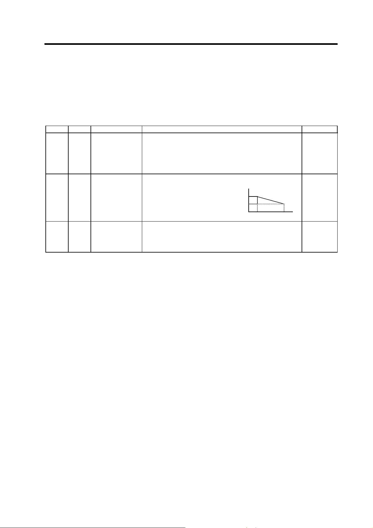
SV006 VGN2 Speed loop gain 2 If the noise is bothersome at high
speed during rapid traverse, etc, lower
the speed loop gain.
As in the right figure, set the speed
loop gain of the speed 1.2 times as
fast as the motor’s rated speed, and
use this with SV029 (VCS).
When not using, set to "0".
0
(Rated speed × 1.2)
-1000 to 1000
SV029 VCS Speed at the change
of speed loop gain
If the noise is bothersome at high speed during rapid traverse, etc,
lower the speed loop gain.
Set the speed at which the speed loop gain changes, and use this with
SV006 (VGN2). (Refer to SV006.)
When not using, set to "0".
0 to 9999
(r/min)
4. Servo Adjustment
4 - 15
4-3-3 Improving the cutting surface precision
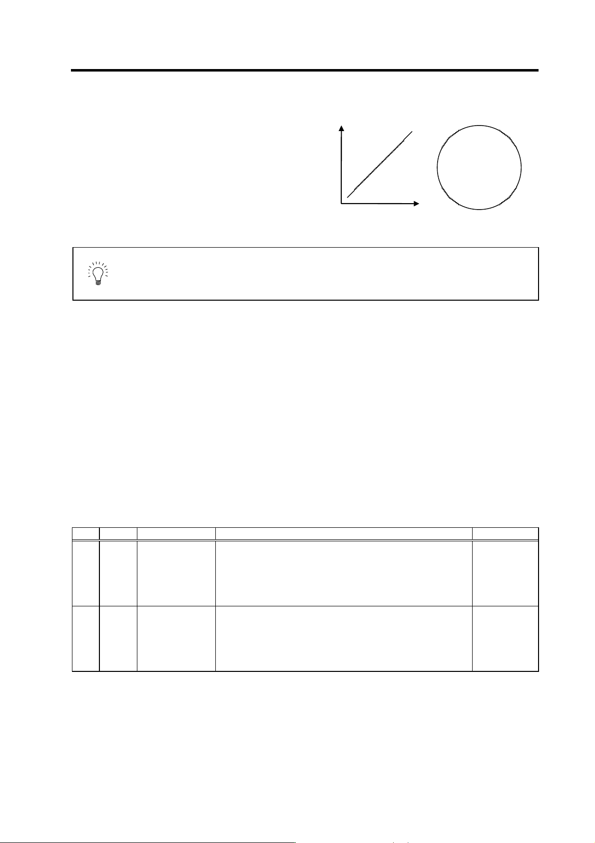
If the cutting surface precision or roundness is poor,
these can be improved by increasing the speed
loop gain (VGN1, VIA) or by using the disturbance
observer function.
<Examples of fault s>
• The surface precision in the 45° direction of a
taper or arc is poor.
• The load fluctuation during cutting is large,
causing vibration or surface precision defects
to occur.
POINT
Adjust by raising the speed loop gain equivalently to improve cutting surface
precision, even if the measures differ. In this case, it is important how much the
machine resonance can be controlled, so adjust making sufficient use of
vibration suppression functions.
(1) Adjusting the speed loop gain (VGN1)
If the speed loop gain is increased, the cutting surface precision will be improved but the machine
will resonate easily.
The final VGN1 setting should be approx. 70 to 80% of the maximum value where resonance does
not occur. (Refer to "4-2-2 (1) Setting the speed loop gain")
(2) Adjusting the speed loop leading compensa tion (VIA)
The VIA has a large influence on the position trackability, particularly during high-speed cutting
(generally F1000 or more). Raising the setting value improves the position trackability, and the
contour precision during high-speed cutting can be improved. For high-speed high-precision
cutting machines, adjust so that a value equal to or higher than the standard value can be set.
When VIA is set lower than the standard value and set to a value differing between interpolation
axes, the roundness may worsen (the circle may distort). This is due to differences occurring in the
position trackability between interpolation axes. The distortion can be improved by matching the
VIA with the smaller of the values. Note that because the position trackability is not improved, the
surface precision will not be improved.
(Refer to "4-2-2 (2) Setting the speed loop leading compensation")
No. Abbrev. Parameter name Explanation Setting range
SV005 VGN1 Speed loop gain 1
Set the speed loop gain.
Set this according to the load inertia size.
The higher the setting value is, the more accurate the control will be,
however, vibration tends to occur.
If vibration occurs, adjust by lowering by 20 to 30%.
The value should be determined to be 70 to 80% of the value at the time
when the vibration stops.
1 to 999
SV008 VIA Speed loop lead
compensation
Set the gain of the speed loop integration control.
The standard setting is "1364". During the SHG control, the standard
setting is "1900". Adjust the value by increasing/decreasing it by about
100 at a time.
Raise this value to improve contour tracking precision in high-speed
cutting. Lower this value when the position droop vibrates (10 to
20Hz).
1 to 9999
X
Y
4. Servo Adjustment
4 - 16
(3) Voltage non-sensitive zone (Td) compensation
With the PWM control of the inverter circuit, a dead time (non-energized time) is set to prevent
short-circuits caused by simultaneous energizing of the P side and N side transistors having the
same phase. The dead time has a non-sensitive zone for particularly low voltage commands. Thus,
when feeding with a low speed and a low torque, the control may be unstable.
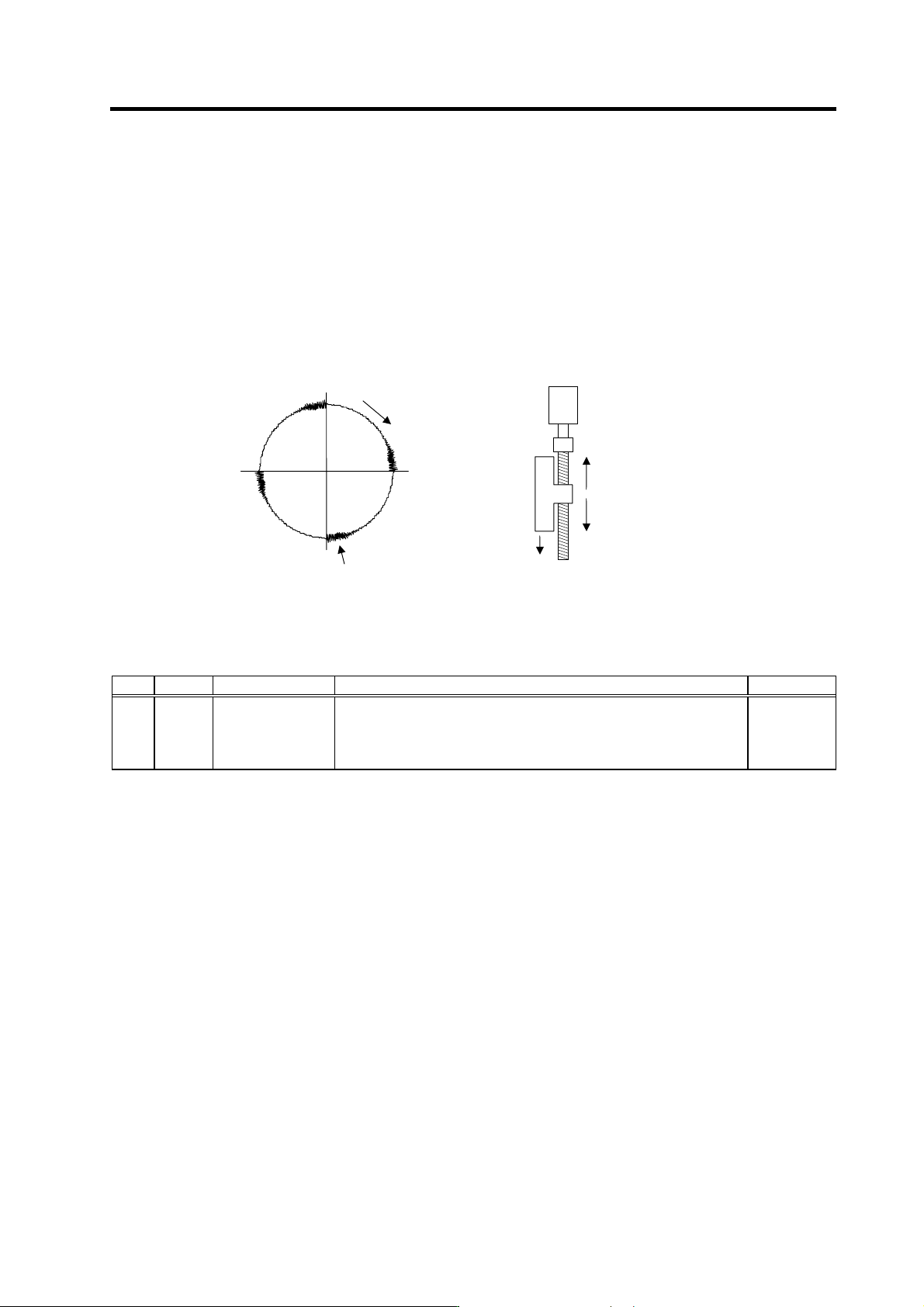
When an unbalanced axis is lowering, the frictional torque and unbalance torque, and the frictional
torque and deceleration torque before the quadrant changes during circle cutting, are balanced.
The motor output torque will be approximately zero, and the control accuracy may drop. In this
case, the control accuracy can be improved by using the voltage non-sensitive band compensation.
Note that this may cause vibration to be increased while the motor is running.
No. Abbrev. Parameter name Explanation Setting range
SV030 IVC
Voltage dead time
compensation
When 100% is set, the voltage equivalent to the logical non-energized time
will be compensated.
When "0" is set, a 100% compensation will be performed.
Adjust in increments of 10% from the default value 100%.
If increased too much, vibration or vibration noise may be generated.
0 to 200
(%)
Frictional torque
Lowering
Balanced
Unbalance torque
For unbalance torque For circle cutting
Cutting direction
Deceleration torque = frictional torque
Motor torque = 0
.
.