bnp-b2365(eng)b.pdf - 第218页
4. Servo Adjustment 4 - 19 4-3-4 Improvement of characteristics during acceleration/deceleration (1) SHG control (option function) Because S HG control has a smoother respon se during acceleration/de celeration than conv…
4. Servo Adjustment
4 - 18
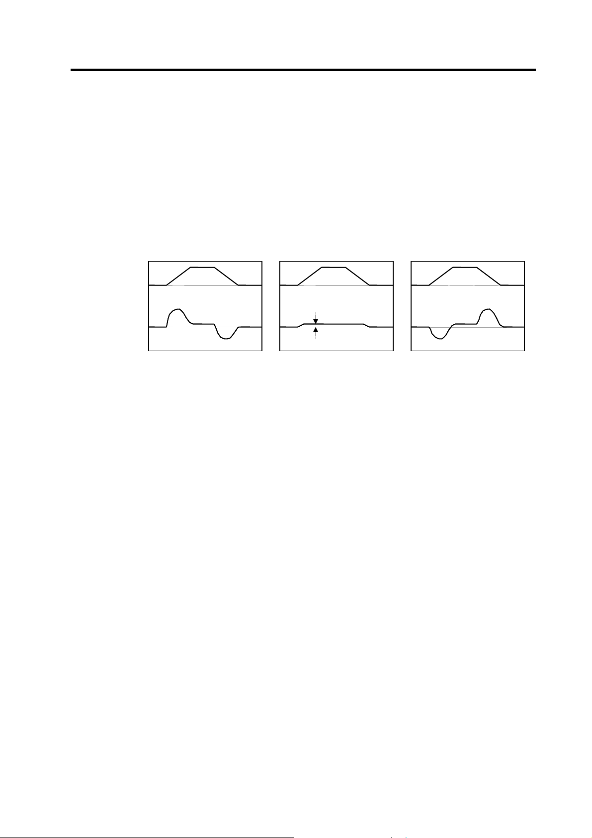
<Measuring the load inertia>
If the load inertia is not clear, it can be estimated with the following method.
[1] Set the torque offset (SV032: TOF) for the unbalance torque. (Refer to "4-3-5 (1) Unbalance
torque and frictional torque".)
[2] Set JL = 100, OBS1 = 600 and OBS2 =0, and reciprocate the axis within the range that it can
be moved smoothly. Set the acceleration/deceleration time constant so that the
acceleration/deceleration torque is larger than the stall (rated) torque (100% or more).
[3] Measure the estimated disturbance torque with the D/A output, and raise JL until the
disturbance torque during acceleration/deceleration is small (until it cannot be observed).
Even if the torque offset is set and JL is an appropriate value, if the axis has a large friction,
the frictional torque will remain in the estimated disturbance torque. Judge the JL setting value,
with frictional torque remaining, as the machine's load inertia scale as shown below.
Speed
command
Estimated
disturbance
torque
0
0
JL: Too small
Time
0
0
JL: Too large
Time
0
0
JL: Appropriate
Time
Frictional
torque
4. Servo Adjustment
4 - 19
4-3-4 Improvement of characteristics during acceleration/deceleration
(1) SHG control (option function)
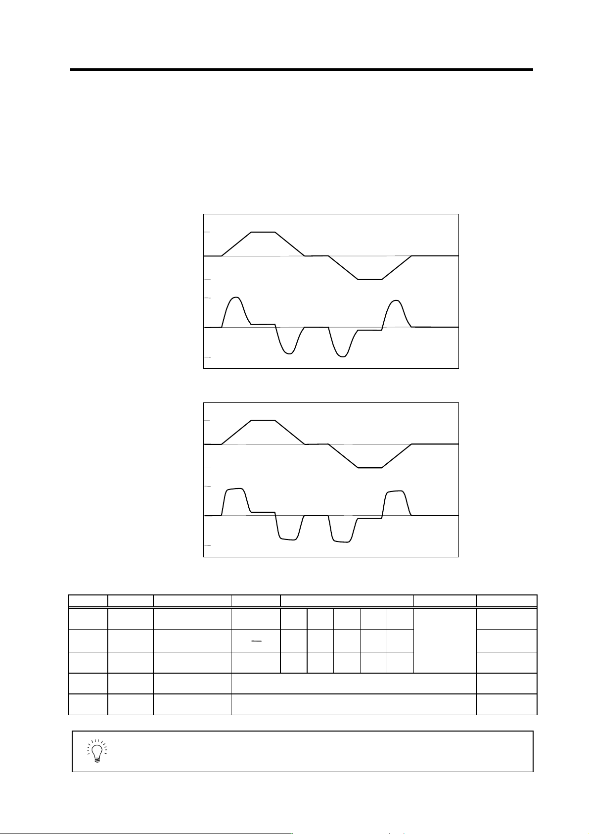
Because SHG control has a smoother response during acceleration/deceleration than
conventional position controls, the acceleration/deceleration torque (current FB) has more ideal
output characteristics (A constant torque is output during acceleration/deceleration.) The peak
torque is kept low by the same acceleration/deceleration time constant, enabling the time constant
to be shortened.
Refer to item "(3) SHG control" in section "4-2-3 Position loop gain" for details on setting SHG
control.
No. Abbrev. Parameter name Setting ratio Setting example Explanation Setting range
SV003
(SV049)
PGN1
(PGN1sp)
Position loop gain 1 1 23 26 33 38 47 1 to 200
SV004
(SV050)
PGN2
(PGN2sp)
Position loop gain 2
8
3
62 70 86 102 125 0 to 999
SV057
(SV058)
SHGC
(SHGCsp)
SHG control gain 6 140 160 187 225 281
Always set with a
combination of
these three
parameters.
0 to 1200
SV008 VIA
Speed loop lead
compensation
Set 1900 as a standard value during SHG control. 1 to 9999
SV015 FFC
Acceleration rate
feed forward gain
Set 100 as a standard value during SHG control. 0 to 999
POINT
SHG control is an option function. If the option is not set in the NC, alarm 37 (at
power ON), or warning E4 and error parameter No. 104 (2304 for M60S/E60
Series NC) will be output.
0
0
3000
200
-200
-3000
0
0
3000
200
-200
-3000
Acceleration/deceleration characteristics during conventional control
Speed command
(r/min)
Current FB
(stall current%)
Time
Time
Acceleration/deceleration characteristics during SHG control
Speed command
(r/min)
Current FB
(stall current %)
Time
Time
4. Servo Adjustment
4 - 20
(2) Acceleration feed forward
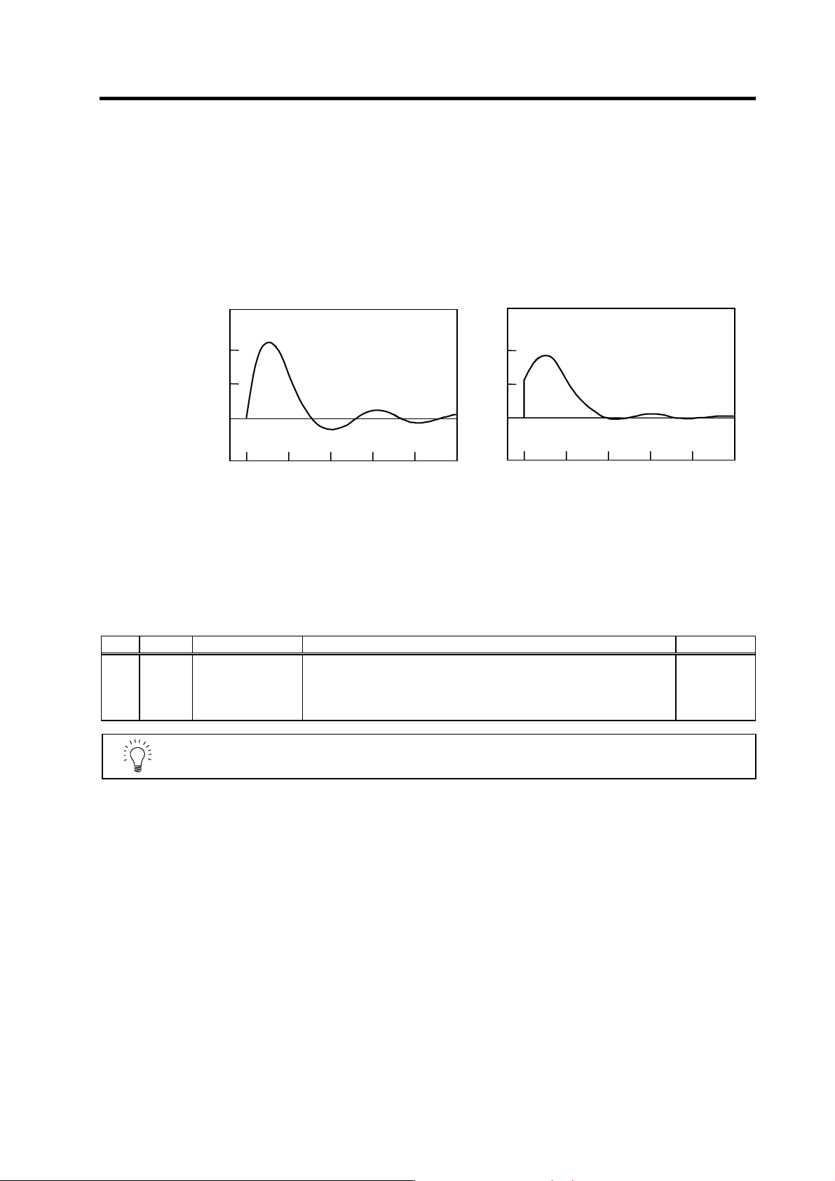
Vibration may occur at 10 to 20 Hz during acceleration/deceleration when a short time constant of
30 ms or less is applied, and a position loop gain (PGN1) higher than the general standard value or
SHG control is used. This is because the torque is insufficient when starting or when starting
deceleration, and can be resolved by setting the acceleration rate feed forward gain (SV015: FFC).
This is also effective in reducing the peak current (torque).
While measuring the current command waveform, increase FFC by 50 to 100 at a time and set the
value where vibration does not occur.
No FFC setting With FFC setting
Acceleration rate feed forward gain means that the speed loop gain during
acceleration/deceleration is raised equivalently. Thus, the torque (current command) required
during acceleration/deceleration starts sooner. The synchronization precision will improve if the
FFC of the delayed side axis is raised between axes for which high-precision synchronous control
(such as synchronous tapping control and superimposition control).
No. Abbrev. Parameter name Explanation Setting range
SV015 FFC Acceleration rate
feed forward gain
When a relative error in the synchronous control is large, apply this
parameter to the axis that is delaying. The standard setting value is "0". For
the SHG control, set to "100".
To adjust a relative error in acceleration/deceleration, increase the value
by 50 to 100 at a time.
0 to 999
(%)
POINT
Overshooting occurs easily when a value above the standard value is set during
SHG control.
Current
command
(%)
200
100
0
100
806040
20 0
Time (ms)
200
100
0
100
8060 40
200
Time (ms)