bnp-b2365(eng)b.pdf - 第221页
4. Servo Adjustment 4 - 22 4-3-5 Improvement of protrusion at quadrant changeover The response delay (caused by dead band from friction, torsion, expansion/contraction, backla sh, etc.) caused when the machine advance d …
4. Servo Adjustment
4 - 21
(3) Inductive voltage compensation
The current loop response is improved by compensating the back electromotive force element
induced by the motor rotation. This improved the current command efficiency, and allows the
acceleration/deceleration time constant to the shortened.
<Adjustment method>
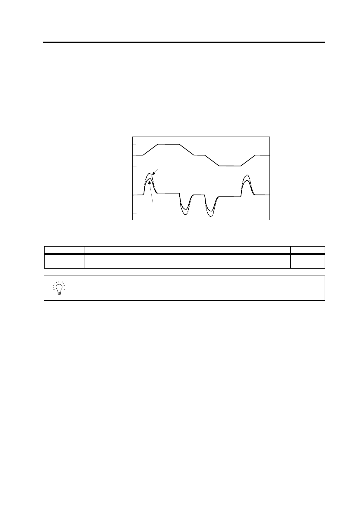
1. While accelerating/decelerating at rapid traverse, adjust the inductive voltage compensation
gain (SV047: EC) so that the current FB peak is a few % smaller than the current command
peak.
Inductive voltage compensation
No. Abbrev. Parameter name Explanation Setting range
SV047 EC Inductive voltage
compensation gain
Set the inductive voltage compensation gain. Set to "100" as a standard.
If the current FB peak exceeds the current command peak, lower the gain.
0 to 200
(%)
POINT
If the current FB peak becomes larger than the current command peak (over
compensation), an overcurrent (alarm 3A) will occur easily. Note that over
compensation will occur easily if the load inertia is large.
0
0
3000
200
-200
-3000
Speed command
(r/min)
Current
command
(Rated current %)
No inductive voltage
compensation
With inductive
voltage
compensation
Time
Time
4. Servo Adjustment
4 - 22
4-3-5 Improvement of protrusion at quadrant changeover
The response delay (caused by dead band from friction, torsion, expansion/contraction, backlash, etc.)
caused when the machine advance direction reverses is compensated with the lost motion compensation
(LMC compensation) function.
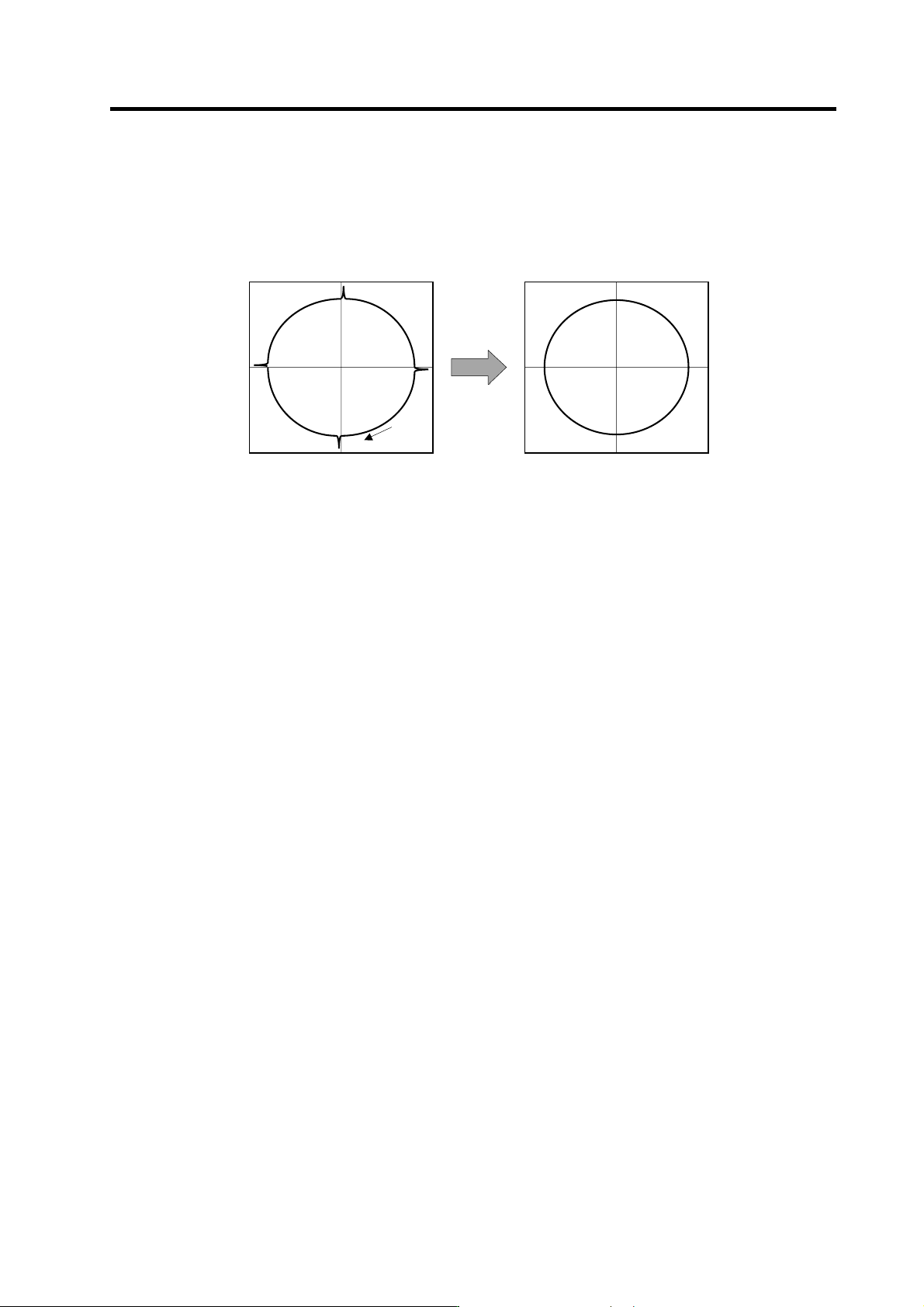
With this, the protrusions that occur at the quadrant changeover in the DBB measurement method, or
the streaks that occur when the quadrant changes during circular cutting can be improved.
The following three compensation types are available for lost motion compensation (LMC compensation).
[1] LMC compensation type 1
This is a backward compatible (for older models) compensation type. Either type 2 or type 3 should
be used on new models.
[2] LMC compensation type 2
Performs servo internal PI control response delay compensation for the frictional torque reversing
condition that occurs during servo reverse travel. Reverse response delay is compensated with
adding the torque command set by parameter when a speed and direction change occurs.
LMC compensation type 2 adjustments should be performed with reference to the following items.
(1) Unbalance torque and frictional torque
(2) LMC compensation type 2 setting and adjustment
(3) Lost motion compensation timing adjustment
(4) Adjustment at feed forward control
[3] LMC compensation type 3
In addition to frictional torque influence, this type compensates torsion and expansion/contraction
influences in the machine system in which compensation amount is changed by travel speed. A
mechanical system viscosity coefficient setting further enhances the compensation accuracy even
if the travel speed is changed. Adjustment requires a machine end roundness measurement.
LMC compensation type 3 adjustments should be performed with reference to the following items.
(1) Unbalance torque and frictional torque
(2) LMC compensation type 3 setting and adjustment
Circle cutting path before compensation
Compensation
Cutting
direction
DBB: Double Ball Bar
Circle cutting path after compensation
4. Servo Adjustment
4 - 23
(1) Unbalance torque and frictional torque
Machine unbalance torque and frictional torque measurements are required before the LMC
compensation can be set. However, the horizontal axis unbalance torque is necessarily "0".
Carry out the reciprocating operation (approx. F1000) with the measured axis, and the load
current % value during constant-speed feed is measured at the NC servo monitor screen. The
unbalance torque and frictional torque at that time are expressed by the following formulas.
Unbalance torque (%) =
(+ feed load current %) + (- feed load current %)
2
Frictional torque (%) =
(+ feed load current %) - (- feed load current %)
2
Assume that the load current % was -55% in the + direction and -25% in the - direction
when JOG feed was carried out at approx. F1000. The unbalance torque and frictional
torque are as shown below.
Unbalance torque (%) =
(-55) + (-25)
2
= -40%
Friction torque (%) =
(-55) - (-25)
2
= 15%
(Example)
(2) Setting and adjusting LMC compensation type 2
<Setting method>
[1] Set the servo function selection 1 (SV027)/bit 9. (The LMC compensation type 2 will start).
[2] Set unbalance torque to the torque offset (SV032).
[3] Set a value double the friction torque to the lost motion compensation 1 (SV016). The SV016
setting value will be used for compensation in the positive and negative directions when the lost
motion compensation 2 (SV041) is 0.
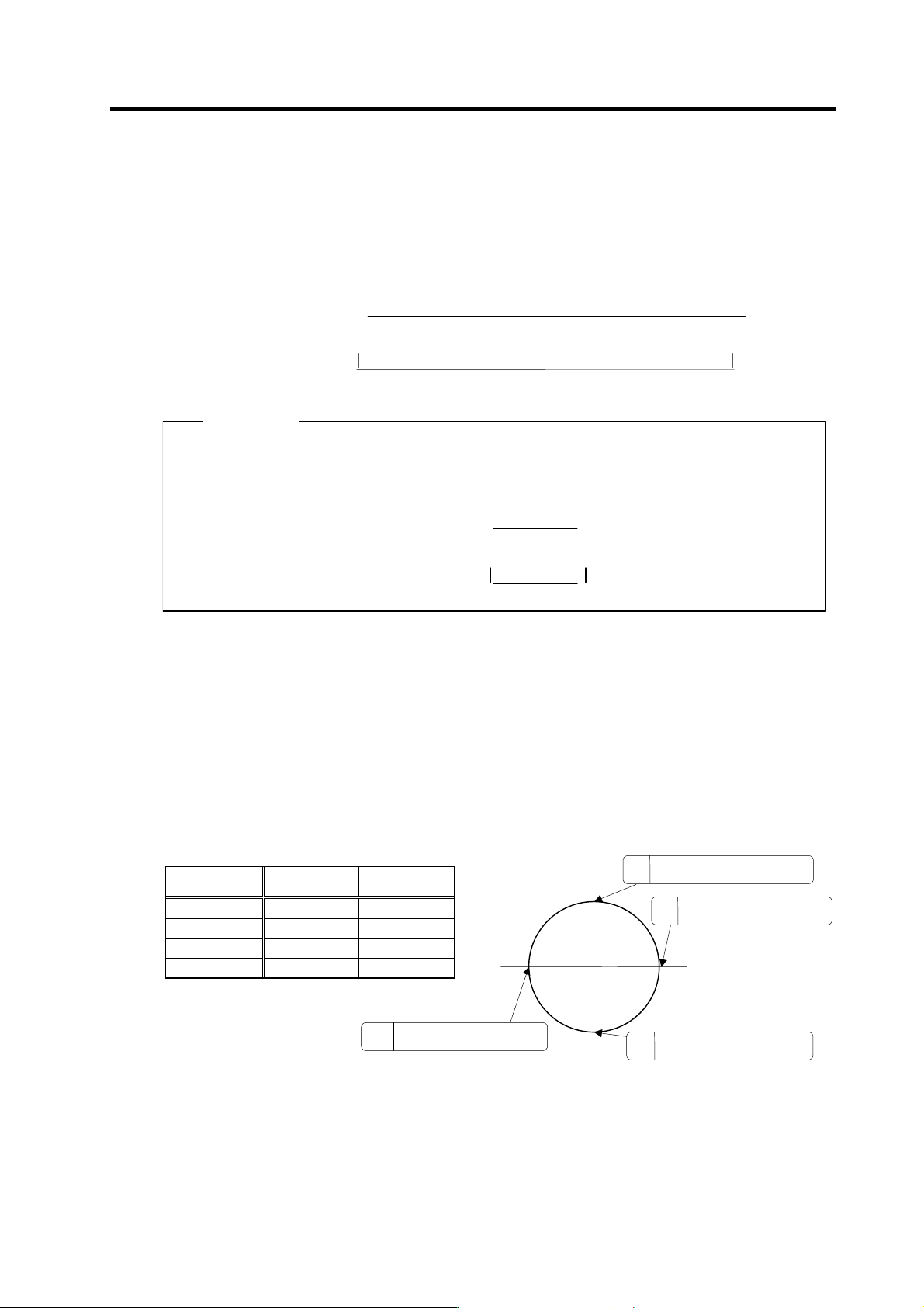
[4] Set SV041, when changing the compensation amount in the direction for compensation. The
setting of the compensation direction is shown below with the setting of CW/CCW in the NC
parameter. If compensating only one direction, set -1 to the side not to be compensated.
Compensation
point
CW CCW
A X axis: SV041 X axis: SV016
B Y axis: SV016 Y axis: SV041
C X axis: SV016 X axis: SV041
D Y axis: SV041 Y axis: SV016
+Y
-Y
+X
-X
A
The X axis command direction
changes from + to -.
D
The Y axis command direction
changes from + to -.
B
The Y axis command direction
changes from - to +.
C
The X axis command direction
changes from - to +.