bnp-b2365(eng)b.pdf - 第229页
4. Servo Adjustment 4 - 30 (2) Adjusting for feed for ward control When using feed forward control (high-speed hig h-a ccuracy control), the f eed forward control must be stopped (fwd_g =0) before adjust ing the over sho…
4. Servo Adjustment
4 - 29
4-3-6 Improvement of overshooting
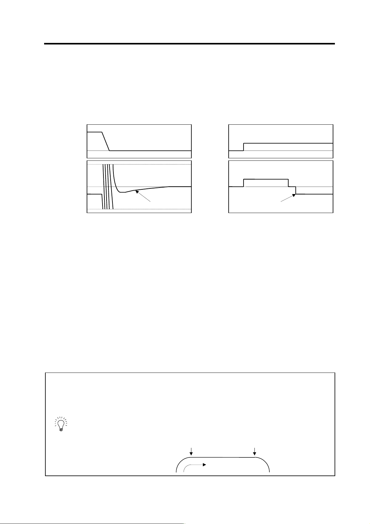
The phenomenon when the machine position goes past or exceeds the command during feed
stopping is called overshooting. Overshooting is compensated by overshooting compensation
(OVS compensation).
Overshooting occurs due to the following two causes.
[1] Machine system torsion: Overshooting will occur mainly during rapid traverse settling
[2] Machine system friction: Overshooting will occur mainly during one pulse feed
Either phenomenon can be confirmed by measuring the position droop.
[1] Overshooting during rapid tr a verse settling [2] Overshooting during pulse feed
(1) Overshooting compensa tion (OVS compensation)
In OVS compensation, the overshooting is suppressed by subtracting the torque command set in
the parameters when the motor stops. There are three types of OVS compensation. Type 3 is the
standard method. (Types 1 and 2 are for compatibility with older models, and thus explanations
have been omitted.)
OVS compensation type 3 has a compensation effect for the overshooting during either rapid
traverse settling or pulse feed. To compensate overshooting during feed forward control, refer to
the following section "(2) Adjusting for feed forward control".
<Setting and adjustment methods>
[1] Set the servo function selection 1 (SV027: SSF1)/bit A, B. (OVS compensation type 3 will start.)
[2] Observe the position droop waveform using the D/A output, and increase the overshooting
compensation 1 (SV031: OVS1) value 1% at a time. Set the smallest value where the overshooting
does not occur. If SV042 (OVS2) is 0, the overshooting will be compensated in both the
forward/reverse directions with the OVS1 setting value.
[3] If the compensation amount is to be changed in the direction to be compensated, set the + direction
compensation value in OVS1 and the - direction compensation value in OVS2. If only one direction is
to be compensated, set the side not to be compensated as -1. The compensation direction setting will
be as reversed with the NC parameter CW/CCW setting.
POINT
1. When either parameter SV031: OVS1 or SV042: OVS2 is set to 0, the same
amount of compensation is carried out in both the positive and negative
direction, using the setting value of the other parameter (the parameter not
set to 0).
2. To compensate in only one direction, set -1 in the parameter (OVS1 or
OVS2) for the direction in which compensation is prohibited.
3. For contour cutting, the projection at the arc end point is compensated with
OVS compensation. LMC compensation is carried out at the arc starting
point.
Cutting direction
LMC compensation
OVS compensation
0
Position
command
0
Position
droop
Time
Overshoo
t
0
Speed
FB
0
Position
droop
Time
Overshoot
4. Servo Adjustment
4 - 30
(2) Adjusting for feed forward control
When using feed forward control (high-speed high-accuracy control), the feed forward control must
be stopped (fwd_g =0) before adjusting the overshooting compensation. After adjusting the
overshooting compensation with normal control, set the overshooting compensation non-sensitive
zone (SV034 (SSF3)/bitC to F (ovsn) to 1 (2µm) and start up feed forward control.
If overshooting compensation is used during feed forward control, the overshooting will increase,
or protrusions could appear during arc cutting. This is because, when the NC is carrying out feed
forward (fwd) control, overshooting equivalent to the operation fraction unit occurs in the position
command, and the OVS compensation is recognized as a change in the command direction,
resulting in compensation in the reverse direction. This can be improved by setting the
overshooting compensation non-sensitive zone width.
If overshooting does not occur during normal control, and occurs only during feed forward control,
adjust the feed forward gain (fwd_g).
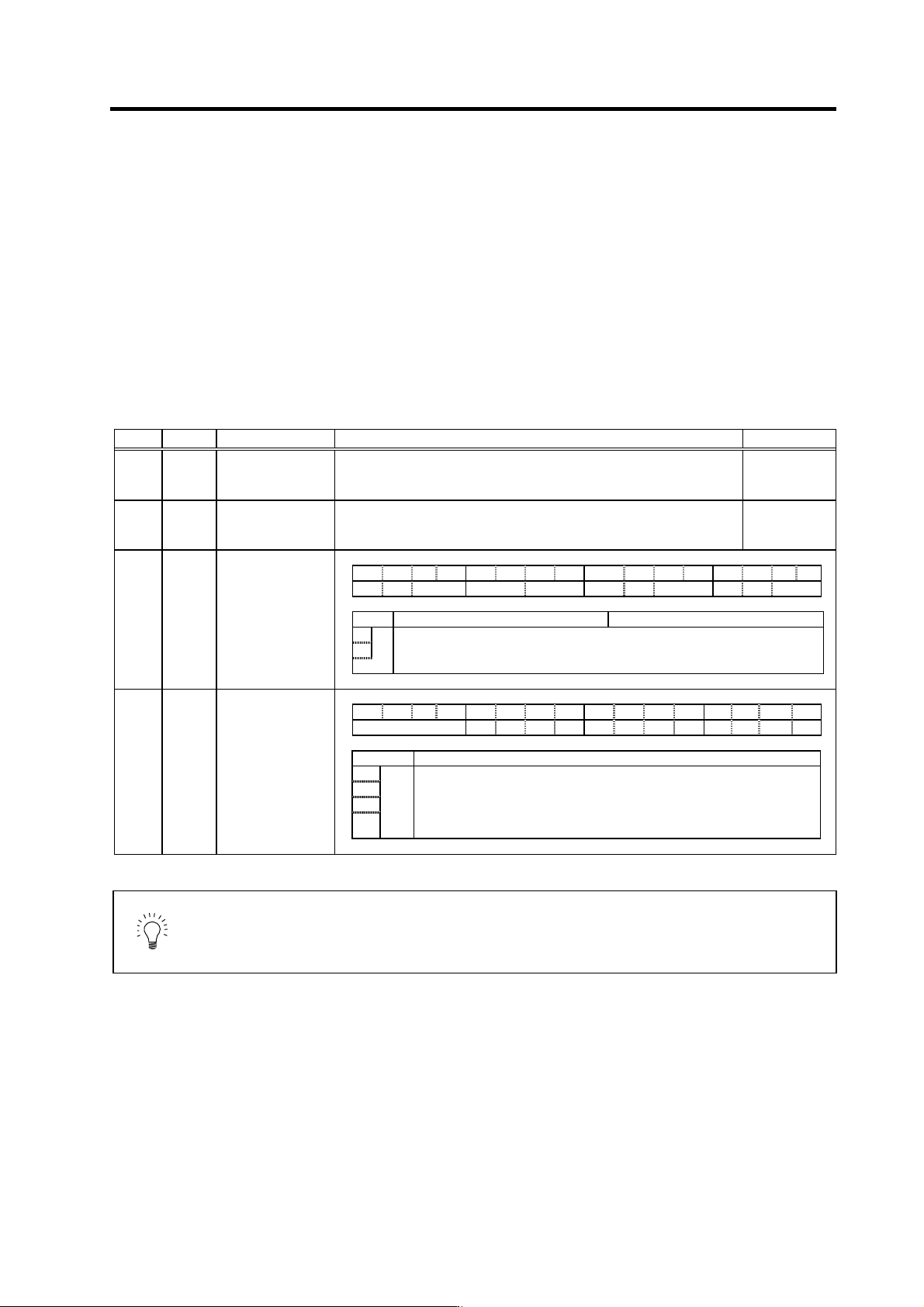
No. Abbrev. Parameter name Explanation Setting range
SV031 OVS1 Overshooting
compensation 1
Increase in increments of 1%, and find the value where overshooting does
not occur. The value is set in both the ± directions when OVS2 is set to 0.
-1 to 100
(Stall [rated]
current %)
SV042 OVS2 Overshooting
compensation 2
Set to "0" as a standard.
Set this to change the compensation amount according to the direction.
-1 to 100
(Stall [rated]
current %)
SV027 SSF1 Servo function
selection 1 F E D C B A 9 8 7 6 5 4 3 2 1 0
aflt zrn2 afse ovs lmc omr zrn3 vfct upc vcnt
bit Meaning when "0" is set Meaning when "1" is set
A Set the compensation amount with SV031 (OVS1) and SV042 (OVS2).
B
ovs
00: Overshooting compensation stop 10: Overshooting compensation type 2
01: Overshooting compensation type1 11: Overshooting compensation type 3
SV034 SSF3 Servo function
selection 3 F E D C B A 9 8 7 6 5 4 3 2 1 0
ovsn has2 has1
bit Explanation
C
D
E
ovsn
F
Set the non-sensitive band of the overshooting compensation type 3 in
increments of 2µm at a time.
In the feed forward control, the non-sensitive band of the model position
droop is set, and overshooting of the model is ignored. Set to the
standard 2µm (0001).
POINT
When using feed forward control (high-speed high-accuracy control), stop the
feed forward control (fwd_g=0) before adjusting the overshooting
compensation. If overshooting occurs during subsequent feed forward control,
adjust the feed forward gain (fwd_g).
4. Servo Adjustment
4 - 31
4-3-7 Improvement of the interpolation control path
(1) Tool end compensation
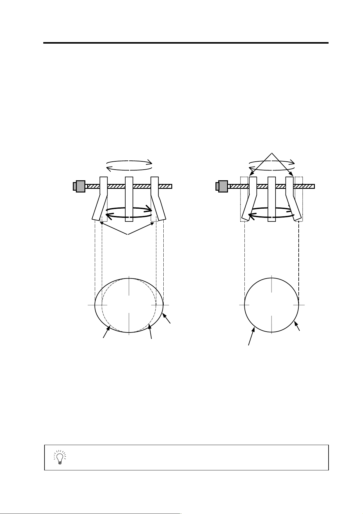
The tool end compensation function compensates the shape of the tool end during high-speed and
high-speed acceleration/deceleration. The spring effect from the tool (spindle) end to the motor
(scale) end is compensated. If the machine has a large spring effect, the shape may be fine during
low-speed operation. However, at high speeds (specially when using a small radius), the section
from the tool (shaft) end to the outer sides of the motor (scale) end could swell, and cause the
shape to become elliptical during measurement of the roundness. The tool end compensation
function compensates the motor end position according to the acceleration size, so the tool end
position is always controlled to the commanded position.
POINT
1. Always evaluate the roundness accuracy at the tool end.
2. Adjust the parameter after adjusting the roundness accuracy at the motor
end.
Without tool end compensation With tool e nd compensation
During high acceleration,
the end section swells
outward due to the spring
effect.
The inner side is driven by the amount
that the end section swells due to the
spring effect.
Tool end roundness
(machining surface)
Elliptical shape fault
Tool end roundness
(machining surface)
Elliptical shape is
improved
Low speed:
Example:
R25mm
F1000mm/min
High speed
(high acceleration):
Example:
R25mm
F10000mm/min
Both low speed and
high speed are on
the same path.
Command path
(ideal path)
Tool end path
(machining surface)
Tool end path
(machining surface)
Command path
(ideal path)