bnp-b2365(eng)b.pdf - 第230页
4. Servo Adjustment 4 - 31 4-3-7 Improvement of the interpolation control path (1) Tool end compensation The tool end compensation function compen sate s the shape of the tool end during high-speed and high-speed acceler…
4. Servo Adjustment
4 - 30
(2) Adjusting for feed forward control
When using feed forward control (high-speed high-accuracy control), the feed forward control must
be stopped (fwd_g =0) before adjusting the overshooting compensation. After adjusting the
overshooting compensation with normal control, set the overshooting compensation non-sensitive
zone (SV034 (SSF3)/bitC to F (ovsn) to 1 (2µm) and start up feed forward control.
If overshooting compensation is used during feed forward control, the overshooting will increase,
or protrusions could appear during arc cutting. This is because, when the NC is carrying out feed
forward (fwd) control, overshooting equivalent to the operation fraction unit occurs in the position
command, and the OVS compensation is recognized as a change in the command direction,
resulting in compensation in the reverse direction. This can be improved by setting the
overshooting compensation non-sensitive zone width.
If overshooting does not occur during normal control, and occurs only during feed forward control,
adjust the feed forward gain (fwd_g).
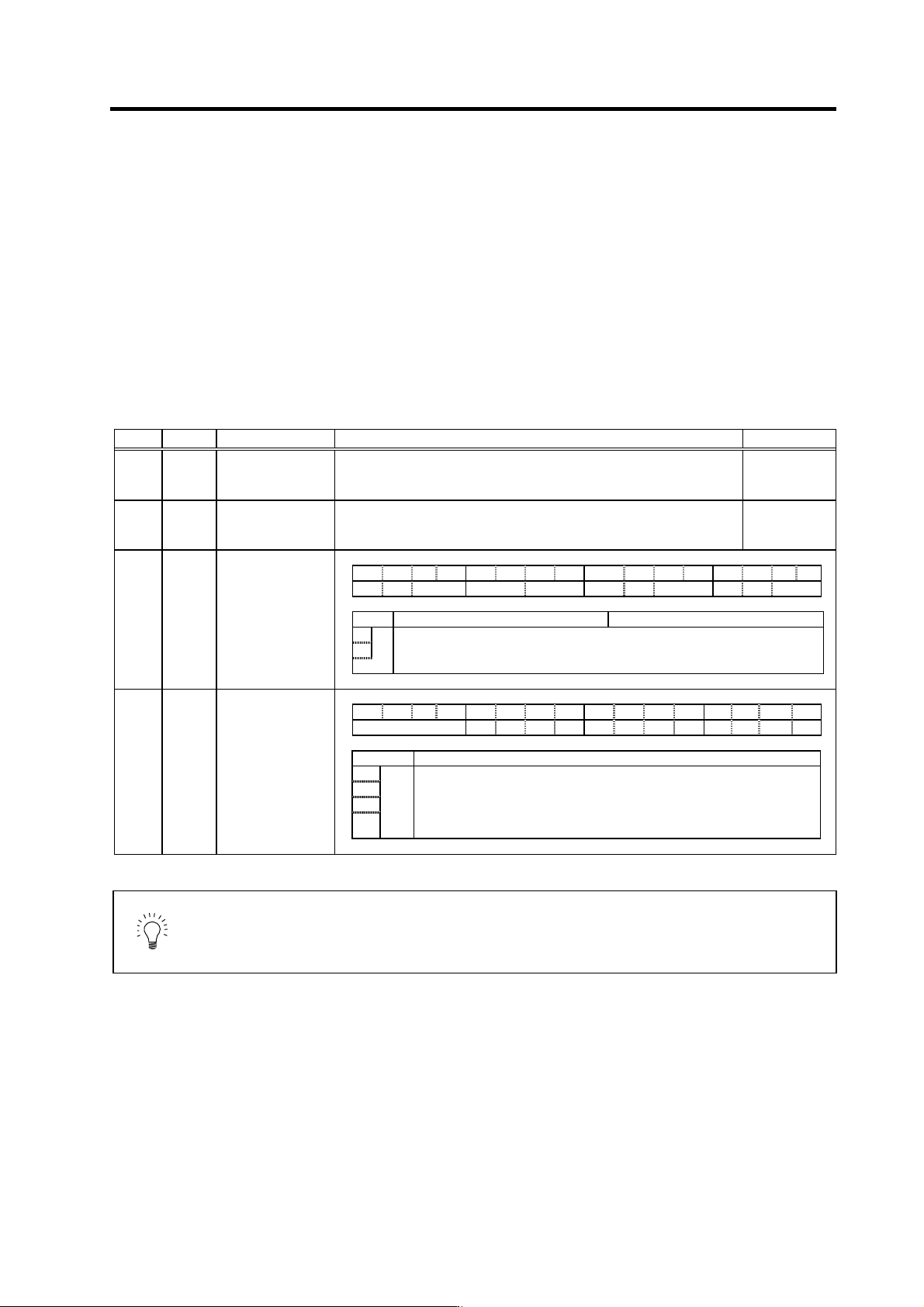
No. Abbrev. Parameter name Explanation Setting range
SV031 OVS1 Overshooting
compensation 1
Increase in increments of 1%, and find the value where overshooting does
not occur. The value is set in both the ± directions when OVS2 is set to 0.
-1 to 100
(Stall [rated]
current %)
SV042 OVS2 Overshooting
compensation 2
Set to "0" as a standard.
Set this to change the compensation amount according to the direction.
-1 to 100
(Stall [rated]
current %)
SV027 SSF1 Servo function
selection 1 F E D C B A 9 8 7 6 5 4 3 2 1 0
aflt zrn2 afse ovs lmc omr zrn3 vfct upc vcnt
bit Meaning when "0" is set Meaning when "1" is set
A Set the compensation amount with SV031 (OVS1) and SV042 (OVS2).
B
ovs
00: Overshooting compensation stop 10: Overshooting compensation type 2
01: Overshooting compensation type1 11: Overshooting compensation type 3
SV034 SSF3 Servo function
selection 3 F E D C B A 9 8 7 6 5 4 3 2 1 0
ovsn has2 has1
bit Explanation
C
D
E
ovsn
F
Set the non-sensitive band of the overshooting compensation type 3 in
increments of 2µm at a time.
In the feed forward control, the non-sensitive band of the model position
droop is set, and overshooting of the model is ignored. Set to the
standard 2µm (0001).
POINT
When using feed forward control (high-speed high-accuracy control), stop the
feed forward control (fwd_g=0) before adjusting the overshooting
compensation. If overshooting occurs during subsequent feed forward control,
adjust the feed forward gain (fwd_g).
4. Servo Adjustment
4 - 31
4-3-7 Improvement of the interpolation control path
(1) Tool end compensation
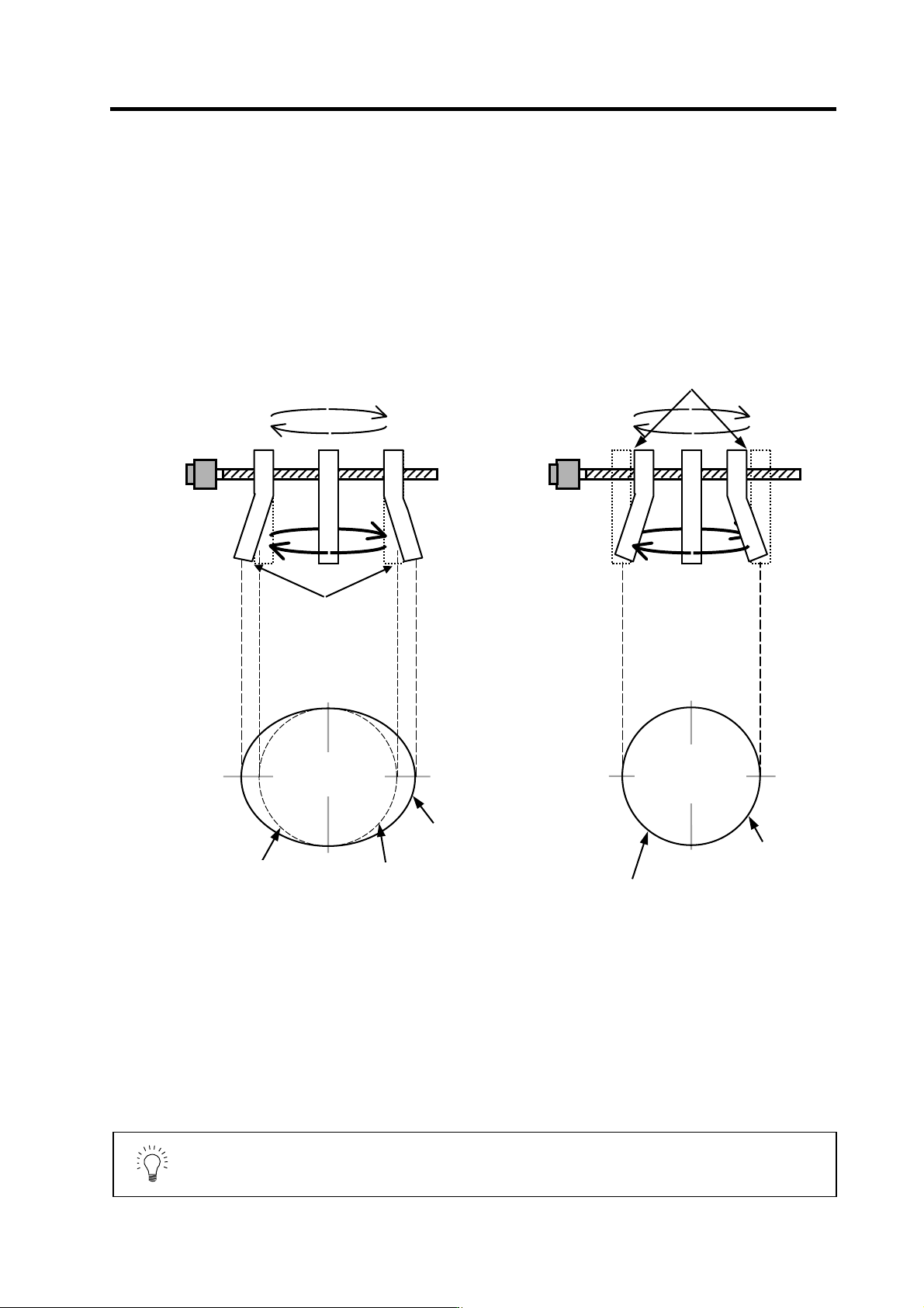
The tool end compensation function compensates the shape of the tool end during high-speed and
high-speed acceleration/deceleration. The spring effect from the tool (spindle) end to the motor
(scale) end is compensated. If the machine has a large spring effect, the shape may be fine during
low-speed operation. However, at high speeds (specially when using a small radius), the section
from the tool (shaft) end to the outer sides of the motor (scale) end could swell, and cause the
shape to become elliptical during measurement of the roundness. The tool end compensation
function compensates the motor end position according to the acceleration size, so the tool end
position is always controlled to the commanded position.
POINT
1. Always evaluate the roundness accuracy at the tool end.
2. Adjust the parameter after adjusting the roundness accuracy at the motor
end.
Without tool end compensation With tool e nd compensation
During high acceleration,
the end section swells
outward due to the spring
effect.
The inner side is driven by the amount
that the end section swells due to the
spring effect.
Tool end roundness
(machining surface)
Elliptical shape fault
Tool end roundness
(machining surface)
Elliptical shape is
improved
Low speed:
Example:
R25mm
F1000mm/min
High speed
(high acceleration):
Example:
R25mm
F10000mm/min
Both low speed and
high speed are on
the same path.
Command path
(ideal path)
Tool end path
(machining surface)
Tool end path
(machining surface)
Command path
(ideal path)
4. Servo Adjustment
4 - 32
<Adjustment methods>
[1] Confirm that the motor end circle accuracy measured with the NC sampling function is
appropriate.
[2] In this state, measure the tool end low-speed and high-speed circle path without tool end
compensation. The difference of the high-speed circle path and low-speed circle path is the
amount that path has swelled due to the spring effect of the machine system. Calculate the
SV065 setting value with the following expression using this amount as the compensation
amount.
SV065 =
Compensation amount [µm] × radius R [mm] ×10
9
(command speed F [mm/min])
2
[3] Set SV027/bit7 to 1, and input the value calculated in step 2 into SV065. Measure the
high-speed circle path. If the shape is still elliptical, adjust by increasing/decreasing the SV065
value in 1/10 units.
[4] Confirm that there is no problem with the low-speed circle path.
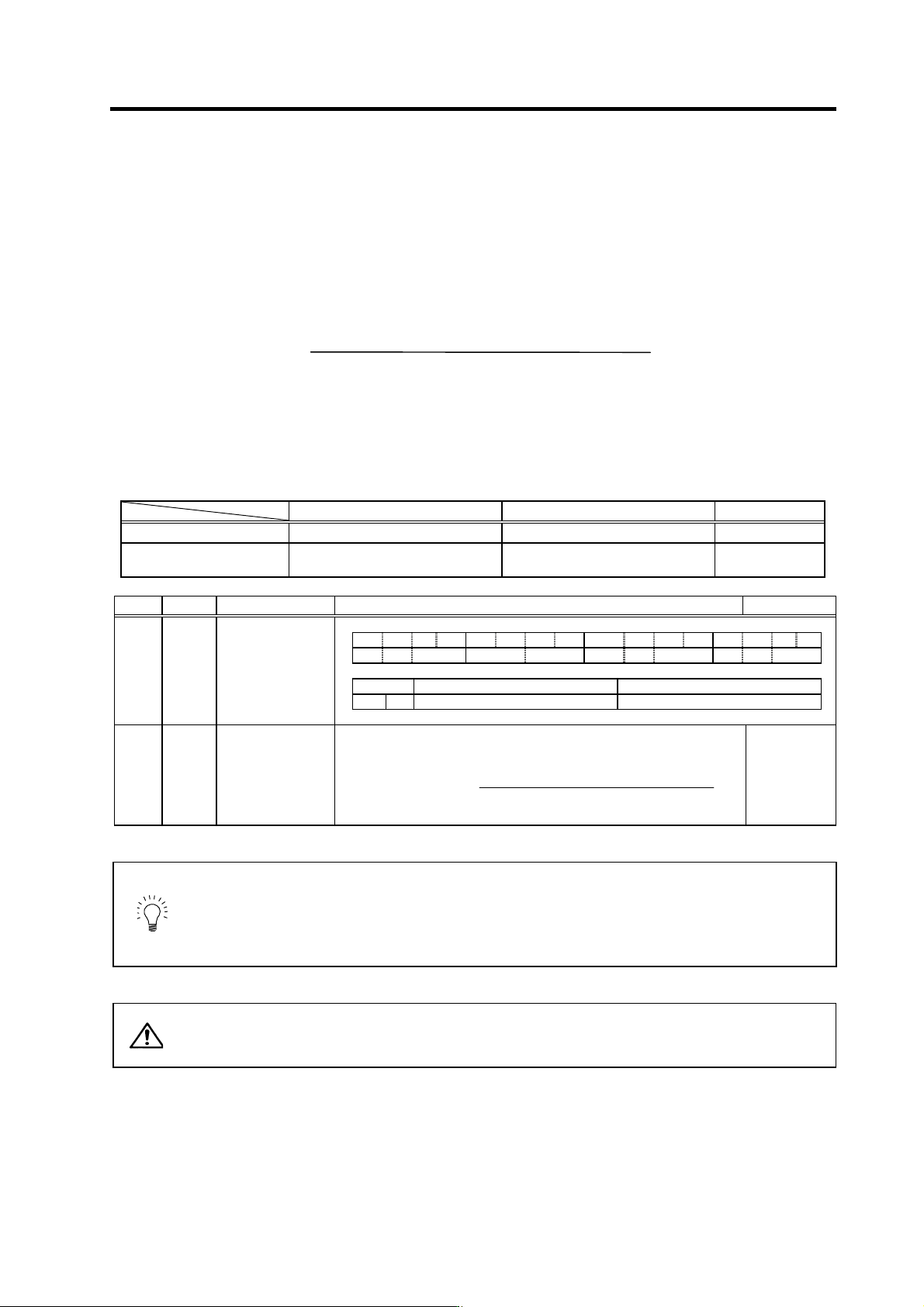
Example of low-speed and high-speed roundness measurement for adjusting tool end compensation
When using grid encoder When using DBB measurement Acceleration
Low speed (reference circle) R=25 [mm], F=500 [mm/min] R=100 [mm], F=1000 [mm/min] 0.00028G
High-speed (when adjusting
compensation amount)
R=25 [mm], F=10000 [mm/min] R=100 [mm], F=20000 [mm/min] 0.11G
No. Abbrev. Parameter name Explanation Setting range
SV027 SSF1 Servo function
selection 1 F E D C B A 9 8 7 6 5 4 3 2 1 0
aflt zrn2 afse ovs lmc omr zrn3 vfct upc vcnt
bit Meaning when "0" is set Meaning when "1" is set
7 omr Tool end compensation invalid Tool end compensation valid
SV065 TLC Tool end
compensation spring
constant
Set the spring constant of the tool end compensation.
In the semi-closed loop control, the tool end compensation amount is
calculated with the following equation.
Compensation amount =
Commanded speed F (mm/min)
2
×
SV065
Radius R (mm)
×
10
9
(µm)
When not using, set to "0".
-32768 to
32767
POINT
1. To confirm the machine's spring element, adjust the electrical end
roundness, and then tool end roundness while changing the cutting speed.
Confirm that the error increases with the speed.
2. The electrical end roundness will have an error on the inner side when tool
end compensation is used.
CAUTION
If an excessive value is set in the tool end compensation spring constant
(SV065), the machine could vibrate when stopping, resulting in a dangerous
state.