bnp-b2365(eng)b.pdf - 第234页
4. Servo Adjustment 4 - 35 4-4-3 Dual feedback control (Optional function) If the motor and machine coupling or machine system 's rigidity is low (ex. large machine, etc.) when using a closed loop syst em, the respo…
4. Servo Adjustment
4 - 34
4-4-2 Speed loop delay compensation
Generally, the tool end position follows the operation later than the motor end position. With full closed
loop position loop control, the tool end position is used for position feedback, so the motor end position
could advance too far and cause the tool end position to overshoot easily. Speed loop delay
compensation suppresses overshooting by weakening the speed loop PI control (weakening advance
compensation = delaying). If the compensation is too large and PI control is weakened too far, the
positioning time could increase, or the position droop will remain when the motor is stopped.
<Adjustment method>
[1] Set the servo function selection 1 (SV027: SSF1)/bit1, bit0 to 10. (Select delay compensation
changeover type 2)
[2] Set the axis unbalance torque to the torque offset (SV032: TOF). (Refer to "4-3-5 (1) Unbalance
torque and frictional torque" for details on measuring the unbalance torque.)
[3] Observe the position droop waveform, and confirm the overshooting. Increase SV007 (VIL) in
increments of 5, and adjust so that the overshooting is improved. If set too high, the position
droop will remain when the axis is stopped.
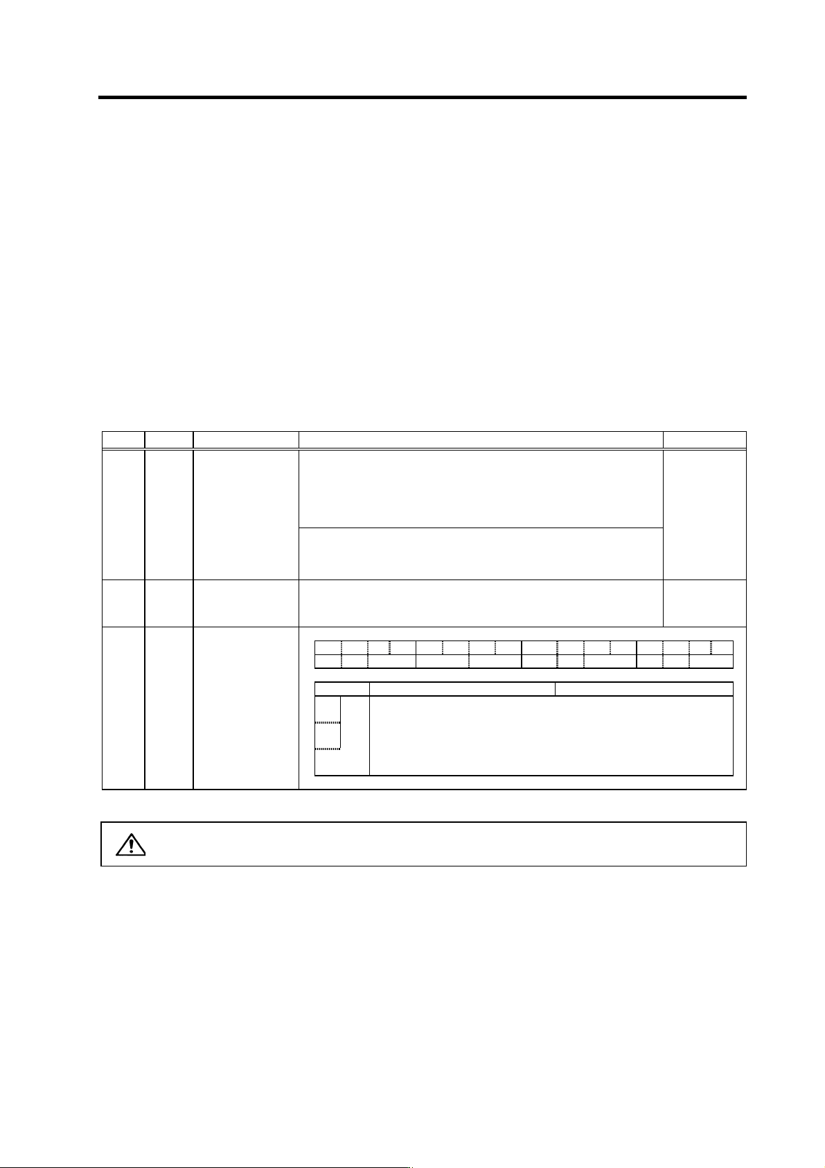
No. Abbrev. Parameter name Explanation Setting range
Set this when the limit cycle occurs in the full-closed loop, or overshooting
occurs in positioning.
Select the control method with SV027 (SSF1)/bit1, 0 (vcnt).
Normally, use "Changeover type 2".
When you set this parameter, make sure to set the torque offset SV032
(TOF). When not using, set to "0".
SV007 VIL
Speed loop delay
compensation
Changeover type 2 When SV027 (SSF1)/ bit1, 0 (vcnt)=10
The delay compensation control works when the command from the
NC is "0" and the position droop is "0". Overshooting or the limit cycle
that occurs during pulse feeding or positioning can be suppressed.
0 to 32767
SV032 TOF Torque offset
Set the unbalance torque of vertical axis and inclined axis.
-100 to 100
(Stall [rated]
current %)
SV027 SSF1 Servo function
selection 1 F E D C B A 9 8 7 6 5 4 3 2 1 0
aflt zrn2 afse ovs lmc omr zrn3 vfct upc vcnt
bit Meaning when "0" is set Meaning when "1" is set
0
Set the execution changeover type of the speed loop delay
compensation.
1
vcnt
00:
Delay compensation changeover
invalid
10: Delay compensation
changeover type 2
01:
Delay compensation changeover
type 1
11: Setting prohibited
CAUTION
The position droop will remain if SV007 is set too high.
4. Servo Adjustment
4 - 35
4-4-3 Dual feedback control (Optional function)
If the motor and machine coupling or machine system's rigidity is low (ex. large machine, etc.) when
using a closed loop system, the response during acceleration/deceleration will vibrate and cause
overshooting. This can cause the position loop gain from increasing. The dual feedback function is
effective in this case.
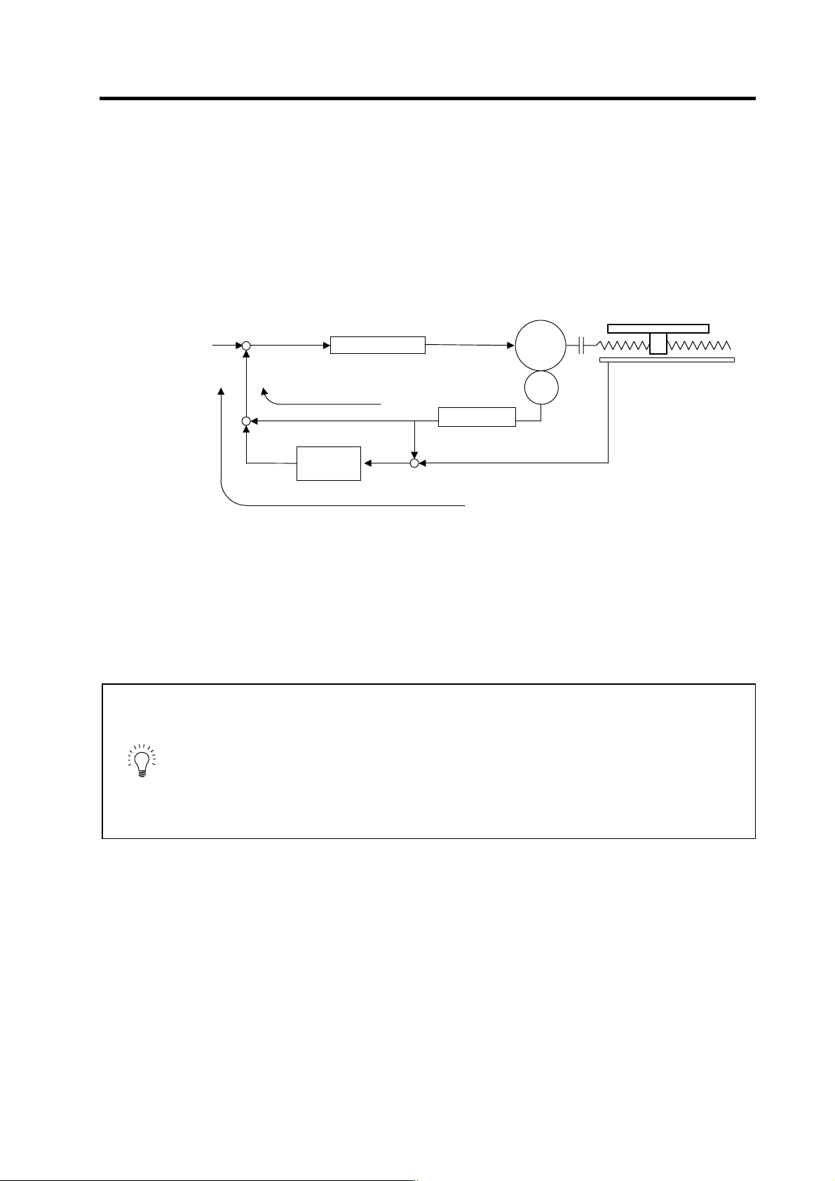
To validate the dual feedback function, use position feedback with a motor end detector in ranges with
high acceleration to enable stable control. In ranges with low acceleration, use position feedback with
the tool end detector (scale). This will make it possible to increase the position loop gain.
Dual feedback control
The state will approach the semi-closed loop system as the primary delay filter's time constant
increases, so the position loop gain limit will increase. Note that the limit of the position loop gain
increased with the dual feedback function is the same as the position loop gain limit for a semi-closed
system that does not use a tool end detector(scale, etc.). In addition, the positioning time will increase
as the primary delay filter time constant increases.
POINT
1. Dual feedback control is a function that compensates symptoms resulting
from insufficient machine rigidity. If there are items that can be improved on
the machine (improvement of scale installation position, etc.) improve those
first.
2. The position loop gain limit will not increase compared to the semi-closed
loop system even when using dual feedback control.
3. Dual feedback control is an optional function. If the option is not set in the
NC, alarm 37 (at power ON), or warning E4 and error parameter No. 103
(2303 for M60S/E60 Series NC) will be output.
Position control
Primary
delay filter
High frequency
FB element
Low frequency
FB element
dead band
SV052
SV051
Position
command
+
-
Position droop
Servo-
motor
ENC
Linear scale
Table
Speed
command
Tool end
p
osition FB
Motor end position FB
+
-
+
-

4. Servo Adjustment
4 - 36
<Adjustment method>
[1] Set the servo specifications (SV017: SPEC)/bit1 to 1, and turn the NC power ON again.
[2] Measure the position droop overshooting while increasing the dual feedback control time
constant (SV051: DFBT) in increments of 5ms. Adjust to the time constant where overshooting
does not occur.
[3] For the final setting value, set a value 1.5 to 2-fold the value adjusted in 3.
No. Abbrev. Parameter name Explanation Setting range
SV017 SPEC* Servo specification
selection F E D C B A 9 8 7 6 5 4 3 2 1 0
spm mpt mp abs vdir fdir vfb seqh dfbx fdir2
bit Meaning when "0" is set Meaning when "1" is set
1 dfbx Dual feedback control stop Dual feedback control start
SV051 DFBT
Dual feedback
control time constant
Set the control time constant in dual feed back.
When "0" is set, the actual value that is set is 1ms.
The higher the time constant is, the closer it gets to the semi-closed
control, so the limit of the position loop gain is raised.
0 to 9999
(ms)
SV052 DFBN
Dual feedback
control non-sensitive
band
Set the non-sensitive band in the dual feedback control.
Set to "0" as a standard.
0 to 9999
(
µm)