bnp-b2365(eng)b.pdf - 第237页
4. Servo Adjustment 4 - 38 No. Abbrev . Parameter nam e Explanation Setting range SV055 EMGx Max. gate off delay time after emergency stop Set a length of time from the point when the em ergency stop is input to the poin…
4. Servo Adjustment
4 - 37
4-5 Settings for emergency stop
Emergency stop in this section refers to the following states.
[1] Emergency stop was input (including other axis alarms)
[2] NC power down was detected
[3] A servo alarm was detected
4-5-1 Deceleration control
With the MDS-C1-V1/V2 servo drive unit, if the deceleration stop function is validated, the motor will
decelerate following the set time constant while maintaining the READY ON state. READY will turn
OFF and the dynamic brakes will function after stopping.
If an alarm, for which dynamic brakes are designated as the stopping method, occurs, the motor will
stop with the dynamic brakes.
<Features>
When the load inertia is large, deceleration stop can be executed at a shorter time than the
dynamic brakes.
(The stop time for the normal acceleration/deceleration time constants will be achieved.)
(1) Setting the deceleration control time constant
Set the time for stopping from the rapid traverse rate (rapid: axis specification parameter) in the
deceleration time constant for emergency stop (SV056: EMGt). The operation stops with the
position loop step when 0 is set.
If linear acceleration/deceleration is selected for rapid traverse, the same value as the
acceleration/deceleration time constant (G0tL) will be the standard value. If another
acceleration/deceleration pattern is selected, set rapid traverse to linear acceleration/deceleration
and adjust to a suitable acceleration/deceleration time constant. Use that value as the standard
value.
<Operation>
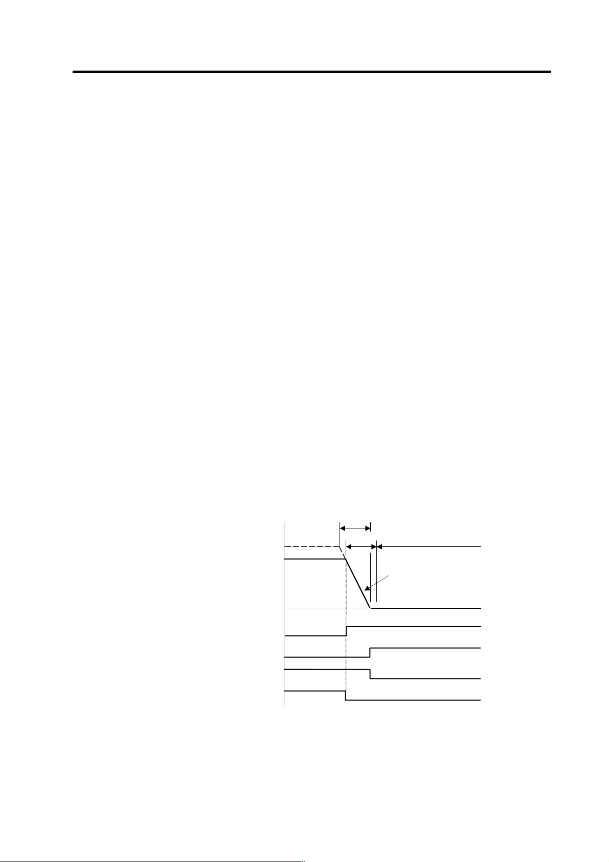
When an emergency stop occurs, the motor will decelerate at the same inclination from each
speed.
Deceleration control sequence
Forced READY OFF range
RAPID
SV056
Constant inclination
decele
r
ation
Motor speed
Time
Motor brake control output (CN20)
OFF
ON
Servo READY (READY)
ON
OFF
In-position (INP)
ON
OFF
READY OFF after in-position
SV055
Emergency stop (EMG)
ON
OFF
4. Servo Adjustment
4 - 38
No. Abbrev. Parameter name Explanation Setting range
SV055 EMGx
Max. gate off delay
time after
emergency stop
Set a length of time from the point when the emergency stop is input to
the point when READY OFF is compulsorily executed.
Normally, set the same value as the absolute value of SV056.
In preventing the vertical axis from dropping, the gate off is delayed for the
length of time set in SV048 if SV055’s value is smaller than that of SV048.
0 to 20000
(ms)
SV056 EMGt
Deceleration time
constant at
emergency stop
In the vertical axis drop prevention time control, set the time constant
used for the deceleration control at emergency stop. Set a length of time
that takes from rapid traverse rate (rapid) to stopping.
Normally, set the same value as the rapid traverse
acceleration/deceleration time constant.
When executing the synchronous operation, put the minus sign to the
settings of both of the master axis and slave axis.
-20000 to
20000 (ms)
(2) Deceleration control stop distanc e
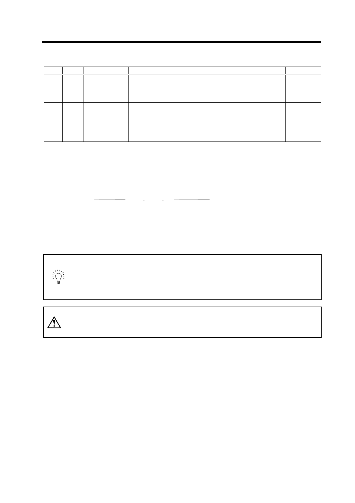
The stopping distance LEMG when the motor is stopped with deceleration control during an
emergency stop can be approximated with the following expression. Note that the value will be
higher than this if the current is limited during deceleration.
L
EMG =
F
PGN1 × 60
+
1
2
×
F
60
×
F × EMGt
ra
p
id × 1000
(mm)
F : Feedrate during emergency stop (mm/min)
rapid : Rapid traverse rate (mm/min)
PGN1 : Position loop gain 1 (SV003) (rad/s)
EMGt : Deceleration time constant for emergency stop (SV056) (ms)
POINT
1. Deceleration control will not take place when a servo alarm, for which the
stopping method is dynamic, occurs. The motor will stop with dynamic
braking regardless of the parameter setting.
2. If the power fails and the deceleration time constant is set to a relatively long
time, the braking method may change from deceleration control to dynamic
braking due to a drop in the bus voltage in the drive unit.
CAUTION
If the deceleration control time constant (EMGt) is set to a value longer than the
acceleration/deceleration time constant, the overtravel point (stroke end point)
may be exceeded.
Take care as the axis could collide with the tool end.
4. Servo Adjustment
4 - 39
4-5-2 Vertical axis drop prevention control
(1) Vertical axis drop prevention control
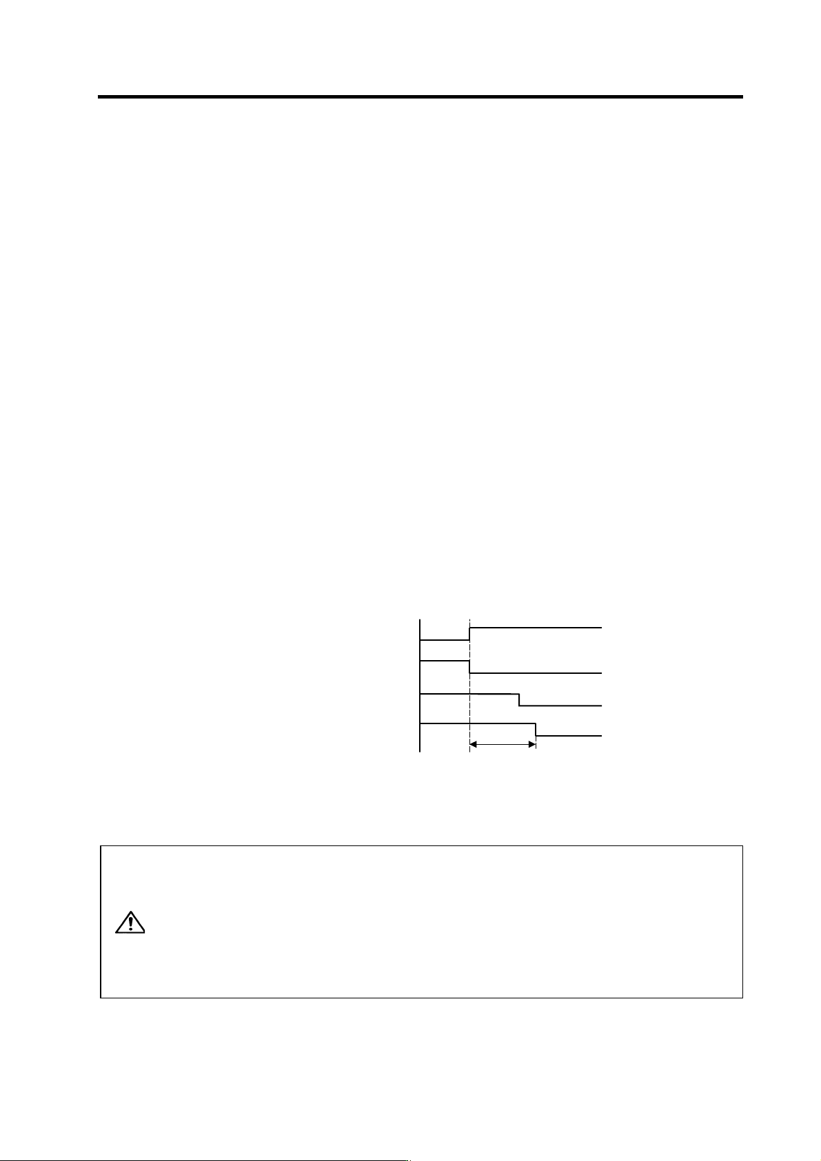
The vertical axis drop prevention control is a function that prevents the vertical axis from dropping due
to a delay in the brake operation when an emergency stop occurs. The no-control time until the brakes
activate can be eliminated by delaying the servo READY OFF state by the time set in the parameters
when an emergency stop occurs.
Always use this function together with deceleration control.
<Setting procedures>
[1] Apply emergency stop while viewing the current position on the NC screen. Adjust the vertical
axis drop prevention time (SV048), and set the minimum delay time at which the axis does not
drop.
[2] Set the same value as the adjusted vertical axis drop prevention time (SV048) for the max. gate
off delay time after emergency stop (SV055).
[3] For the axis for which the vertical drop is to be controlled, set the same value as the
acceleration/deceleration time constant for the deceleration control time constant at emergency
stop (SV056).
[4] If the vertical axis is MDS-C1-V2 (2-axis drive unit), set the servo parameters for the other axis
in the same unit.
SV048 = Same value as adjusted vertical axis SV048
SV055 = Same value as adjusted vertical axis SV055
SV056 = Same value as that axis' rapid traverse acceleration/deceleration time constant
[5] Set the spindle parameter SP033/bitF=1 when the converter that supplies PN power to the
vertical axis is controlled by the spindle amplifier.
[6] If the converter that supplies PN power to the vertical axis is controlled by a different servo
amplifier, set the servo parameter setting for that axis as well. (Same as item [4] above).
Vertical axis drop prevention control sequence
CAUTION
1. Always set deceleration control when using the vertical axis drop
prevention control setting.
2. Configure so that the power supply unit is controlled directly by the servo
drive unit which controls the spindle drive unit or the vertical axis drop
prevention control.
3. If an alarm, for which dynamic brake stopping is designated, occurs with
the axis for which vertical axis drop prevention control is active, the function
will not activate. To prevent axis dropping under all conditions, provide
measures on the machine side by installing a balance unit, etc.
Motor brake control output (CN20)
OFF
ON
Servo READY (READY)
ON
OFF
Emergency stop (EMG)
ON
OFF
SV048
Motor brake actual operation (BRK)
OFF
ON