bnp-b2365(eng)b.pdf - 第242页
4. Servo Adjustment 4 - 43 4-6 Protective functions 4-6-1 Overload detection The servo drive unit is equipped with a n electronic ther mal that protects the servomotor and servo drive unit from overload conditions. The o…
4. Servo Adjustment
4 - 42
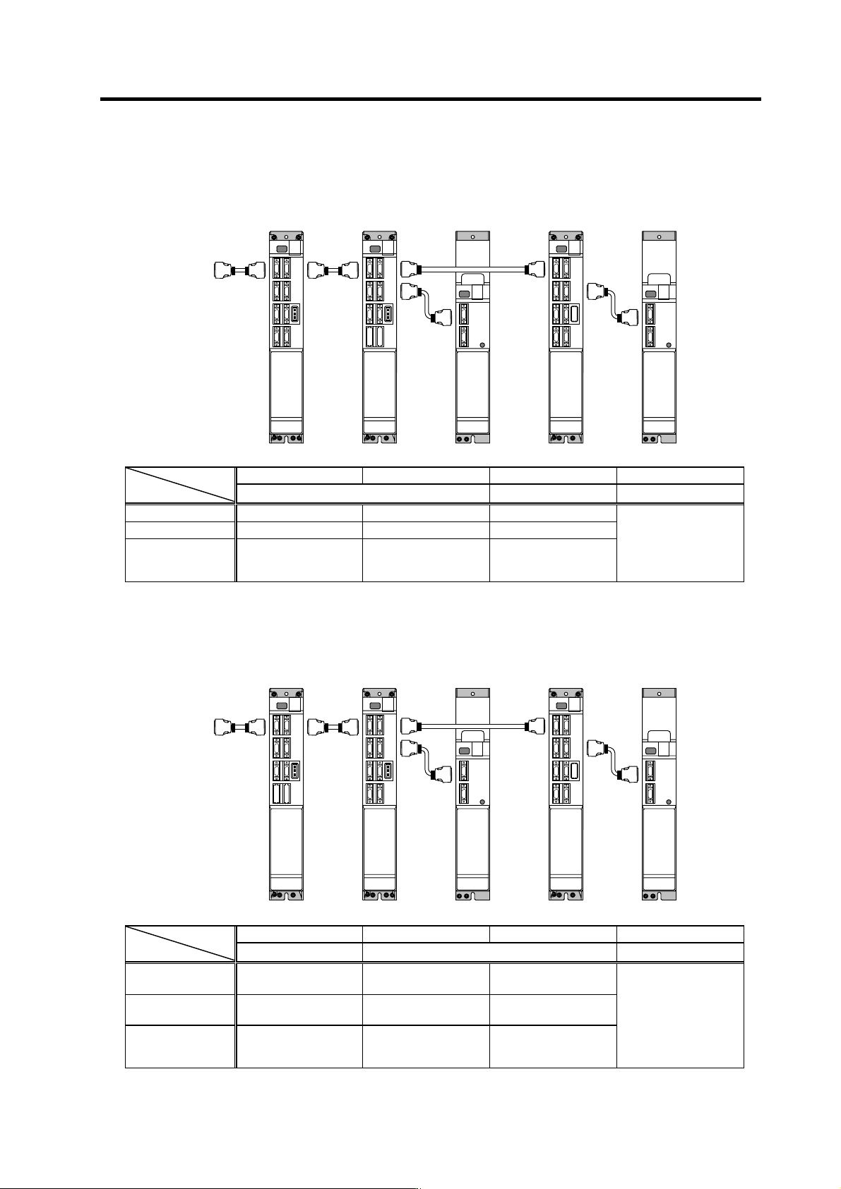
[3] Servo controls power supply, vertical axis is a 1-axis unit (vertical axis: Z axis)
MDS-C1-V2
X axis, Y axis
MDS-C1-V1
*Z axis
MDS-C1-CV
Power supply
MDS-C1-SP
Spindle
MDS-C1-CV
Power supply
X axis Y axis Z axis (Vertical axis) Spindle
Axis
Parameter
MDS-C1-V2 MDS-C1-V1 MDS-C1-SP
SV048 - - Set by adjustment
SV055 - - Same value as SV048
SV056 - -
Same value as Z axis
rapid traverse time
constant
No spindle parameter
setting required
[4] Servo controls power supply, vertical axis is a 2-axis unit (vertical axis: Z axis)
MDS-C1-V1
X axis
MDS-C1-V2
Y axis, *Z axis
MDS-C1-CV
Power supply
MDS-C1-SP
Spindle
MDS-C1-CV
Power supply
X axis Y axis Z axis (Vertical axis) Spindle
Axis
Parameter
MDS-C1-V1 MDS-C1-V2 MDS-C1-SP
SV048 -
Same value
as Z axis
→
Set by adjustment
SV055 -
Same value
as Z axis
→
Same value as SV048
SV056 -
Same value as Y axis
rapid traverse time
constant
Same value as Z axis
rapid traverse time
constant
No spindle parameter
setting required
NC
NC
4. Servo Adjustment
4 - 43
4-6 Protective functions
4-6-1 Overload detection
The servo drive unit is equipped with an electronic thermal that protects the servomotor and servo drive
unit from overload conditions. The overload 1 alarm (alarm 50) is detected if an overload condition
occurs, and the overload 2 alarm (alarm 51) is detected if 95% or more of the maximum current is
commanded continuously for 1 second or longer due to a machine collision, etc. The parameters
shown below are for machine tool builder adjustment purposes only, and should be kept at their
standard settings (SV021=60, SV022=150).
For details concerning the overload protection characteristics, refer to the MDS-C1 Series Specifications
Manual (BNP-C3040).
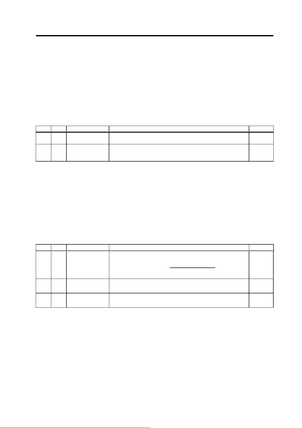
No. Abbrev. Parameter name Explanation Setting range
SV021 OLT
Overload detection
time constant
Set the detection time constant of Overload 1 (Alarm 50).
Set to "60" as a standard. (For machine tool builder adjustment.)
1 to 999
(s)
SV022 OLL
Overload detection
level
Set the current detection level of Overload 1 (Alarm 50) in respect to the
stall (rated) current.
Set to "150" as a standard. (For machine tool builder adjustment.)
110 to 500
(Stall [rated]
current %)
4-6-2 Excessive error detection
An excessive error (alarms 52, 53, 54) is detected when the difference between the servo's
commanded position and the FB position exceeds the value set by parameter. Separate excessive
error detection width can be set for servo ON (SV023) and servo OFF (SV026) statuses. When a wider
excessive error detection width than that used for standard control is required in stopper control, etc.,
the detection width setting can be changed to the SV053 setting value by NC command.
Follow-up control (NC commanded position tracks servo FB position) is used during emergency stop
and during a servo OFF command, and so there is no excessive error detection at those times,
although the follow-up control during a servo OFF status can be disabled by an NC system parameter
setting.
No. Abbrev. Parameter name Explanation Setting range
Set the excessive error detection width when servo ON.
Rapid traverse rate
(mm/min)
<Standard
setting value>
OD1=OD2=
60
× PGN1
÷ 2 (mm)
SV023 OD1
Excessive error
detection width
during servo ON
When "0" is set, the excessive error detection will not be performed.
0 to 32767
(mm)
SV026 OD2
Excessive error
detection width
during servo OFF
Set the excessive error detection width when servo ON.
For the standard setting, refer to the explanation of SV023 (OD1).
When "0" is set, the excessive error detection will not be performed.
0 to 32767
(mm)
SV053 OD3
Excessive error
detection width in
special control
Set the excessive error detection width when servo ON in a special control
(initial absolute position setting, stopper control, etc.).
If "0" is set, excessive error detection won’t be performed.
0 to 32767
(mm)
4. Servo Adjustment
4 - 44
4-6-3 Collision detection
Collision detection quickly detects a collision of the motor shaft, and decelerates and stops the motor.
This suppresses the generation of an excessive torque in the machine tool, and helps to prevent an
abnormal state from occurring. Impact at a collision will not be prevented by using this collision
detection function, so this function does not necessarily guarantee that the machine tool will not be
damaged or that the machine accuracy will be maintained after a collision. The same caution as during
regular operation is required to prevent the machine from colliding.
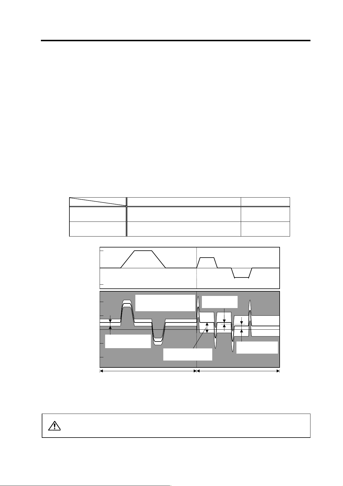
(1) Collision detection method 1
The required torque for the command is estimated from the position command issued from the NC,
and the disturbance torque is obtained from the difference with the actual torque. When this
disturbance torque exceeds the collision detection level set with the parameters, the motor will
decelerate to a stop with a torque 80% (standard) value of the motor's maximum torque. After
decelerating to a stop, alarm 58 or 59 will occur, and the system will stop.
The collision detection level for rapid traverse (G0) is set with SV060: TLMT. The collision
detection level for cutting feed (G1) is set to 0 to 7-fold (SV35.clG1) based on the collision
detection level for rapid traverse. When clG1 is set to 0, collision detection method 1 will not
function during cutting feed. If SV060 is set to 0, all collision detection (including methods 1 and 2)
will not function.
Collision detection level setting parameter Detected alarm
During rapid traverse
(During G0 feed)
SV060 Alarm 58
During cutting feed
(During G1 feed)
SV060 × c1G1 (SV035) Alarm 59
Alarm detection range for collision detection method 1
CAUTION
The collision detection function does not guarantee safety or machine
accuracy when a collision occurs. Thus, the same caution as during regular
operation is required to prevent the machine from colliding.
Speed command
(r/min)
0
Estimated torque
(stall%)
0
3000
200
100
-200
-100
-3000
Unbalance torque
(SV032)
G0 collision detection
level (SV060)
Collision detection method 1,
detection range
(alarm 58/59)
Frictional torque
(SV045)
G1 feed
(
cuttin
g
feed
)
G0 feed
(
ra
p
id traverse
)
G1 collision detection
level
(
SV060×clG1
)