bnp-b2365(eng)b.pdf - 第246页
5. Spindle Adjustment 5 - 1 5-1 D/A output specificati ons for spindl e drive unit .......................................................................... ....... 5-2 5-1-1 D/A output spec ifications .................…
4. Servo Adjustment
4 - 46
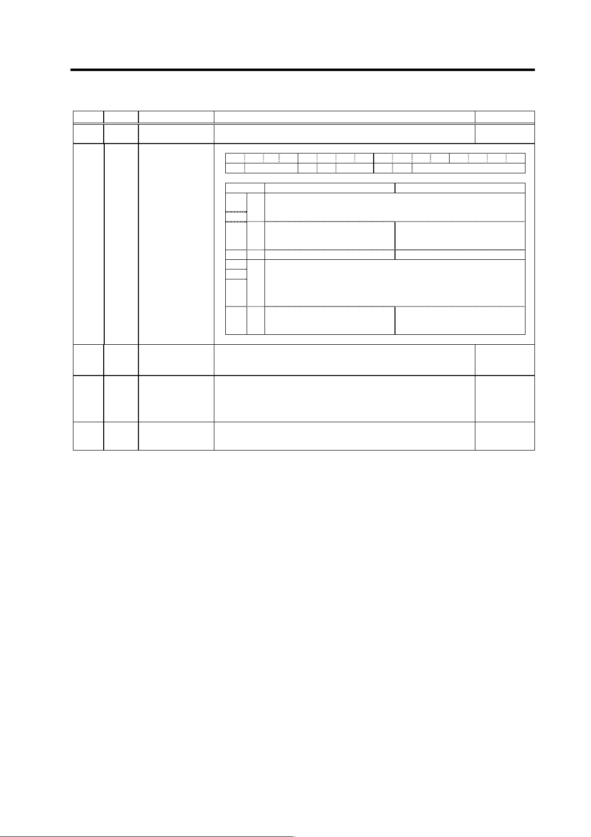
No. Abbrev. Parameter name Explanation Setting range
SV032 TOF Torque offset
Set the unbalance torque of vertical axis and inclined axis. -100 to 100
(Stall current %)
SV035 SSF4 Servo function
selection 4 F E D C B A 9 8 7 6 5 4 3 2 1 0
clt clG1 cl2n clet cltq iup tdt
bit Meaning when "0" is set Meaning when "1" is set
8
Set the retracting torque for collision detection in respect to the maximum
torque of the motor.
9
cltq
00 : 100% 01 : 90% 10 : 80% (Standard) 11 : 70%
A clet
Setting for normal use The disturbance torque peak of the
latest two seconds is displayed in
MPOS of the servo monitor screen.
B cl2n Collision detection method 2 valid Collision detection method 2 invalid
C
D
E
clG1
Collision detection method 1
Set the collision detection level during cutting feed (G1).
The G1 collision detection level=SV060
× clG1.
When clG1=0, the collision detection method 1 during cutting feed won’t
function.
F clt
Setting for normal use The guide value of the SV059
setting value is displayed in MPOS
of the servo monitor screen.
SV045 TRUB
(Low
order)
Frictional torque
When you use the collision detection function, set the frictional torque. 0 to 100
(Stall current %)
SV059 TCNV Collision detection
torque estimating
gain
Set the torque estimating gain when using the collision detection function.
After setting as SV035/bitF(clt)=1 and performing
acceleration/deceleration, set the value displayed in MPOS of the NC
servo monitor screen.
Set to "0" when not using the collision detection function.
-32768 to
32767
SV060 TLMT Collision detection
level
When using the collision detection function, set the collision detection
level during the G0 feeding.
If "0" is set, none of the collision detection function will work.
0 to 999
(Stall current %)

5. Spindle Adjustment
5 - 1
5-1 D/A output specifications for spindle drive unit................................................................................. 5-2
5-1-1 D/A output specifications ........................................................................................................... 5-2
5-1-2 Setting the output data............................................................................................................... 5-3
5-1-3 Setting the output magnification ................................................................................................ 5-4
5-2 Spindle control signal........................................................................................................................ 5-6
5-2-1 Spindle control input (NC to SP) ................................................................................................ 5-6
5-2-2 Spindle control output (SP to NC)............................................................................................ 5-15
5-3 Adjustment procedures for each control......................................................................................... 5-26
5-3-1 Basic adjustments.................................................................................................................... 5-26
5-3-2 Adjusting the acceleration/deceleration operation................................................................... 5-27
5-3-3 Adjusting the orientation control .............................................................................................. 5-36
5-3-4 Adjusting the synchronous tap control..................................................................................... 5-50
5-3-5 Adjusting the C-axis control ..................................................................................................... 5-54
5-3-6 Adjusting the spindle synchronous control .............................................................................. 5-57
5. Spindle Adjustment
5 - 2
5-1 D/A output specifications for spindle drive unit
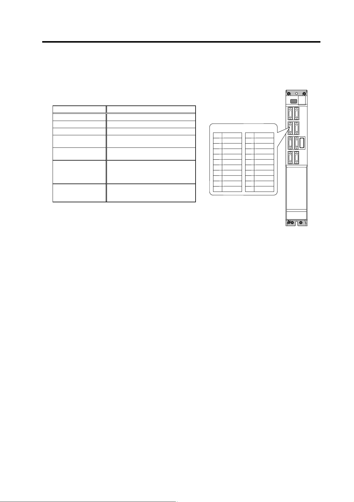
The MDS-C1-SP/SPH/SPX/SPHX/SPM spindle drive unit has a function to D/A output each control
data. The spindle adjustment data requi red to set the spindle pa rameters match ing the machine ca n be
D/A output. The data can be measured with a hi-corder or oscilloscope, etc.
5-1-1 D/A output specifications
Item Explanation
No. of channels 2ch
Output cycle 444µs (min. value)
Output precision 8bit
Output voltage range
0V to +5V (zero) to +10V,
0V to +10V for meter output
Output magnification
setting
±1/256 to ±128-fold
Output pin
CN9 connector
MO1 = Pin 9
MO2 = Pin 19
GND = Pin 1
Function
Phase current feedback output function
U phase current FB : Pin 7
V phase current FB : Pin 17
MO19
Name
LG
UIFB
2
5
1
Pin
6
4
3
10
7
8
CN9 connector
MO2 19
Name
VIFB
12
15
11
Pin
16
14
13
20
17
18