bnp-b2365(eng)b.pdf - 第250页
5. Spindle Adjustment 5 - 5 (3) Control signal output (Data No. 80 to 87) A hexadecimal display is converted into a decimal and output. The method of calculating the magnification is the same as (2). The status ca nnot b…
5. Spindle Adjustment
5 - 4
5-1-3 Setting the output magnification
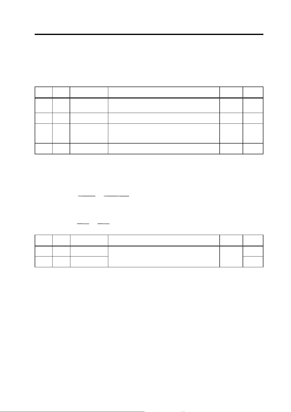
(1) Meter output (Data No. 0)
With meter output, the output channel is fixed, and the output voltage range is 0 to 10V in the
positive range. Set the magnification with the following parameters. Also, low path filter can be set
on the load meter output.
No. Abbr. Parameter name Details
Setting
range
Standard
SP017 TSP* Maximum motor
speed
Set the maximum spindle motor speed.
When SP249=0, the motor speed will be the motor rotation
speed at the speedometer 10V output.
1 to 32767
(r/min)
6000
SP094 LMAV* Load meter output
filter
Set the filter time constant of load meter output.
When "0" is set, a filter time constant is set to 100ms.
0 to 32767
(2ms)
0
SP249 SMO Speedometer speed Set the motor rotation speed when the speedometer 10V is
output.
When set to "0", this parameter becomes the same as SP017
(TSP).
0 to 32767
(r/min)
0
SP250 LMO Load meter voltage Set the voltage when the load meter 120% is output. When set
to "0", this becomes 10V.
0 to 10
(V)
0
(2) Internal data output (D at a No. 1 to 13)
Normally, the standard setting value is set for the output magnification (SP255, SP256). When
"0" is set, the magnification will be the same as "256".
DATA ×
SP255
256
×
10 [V]
256
(
8 bit
)
+ 5 [V] (offset) = Output voltage [V]
(Example) To output current FB at a 30-minute stall rating 20%/V unit (SP253=3, SP255=8)
819.2 ×
8
256
×
10
256
+ 5 = 6 [V]
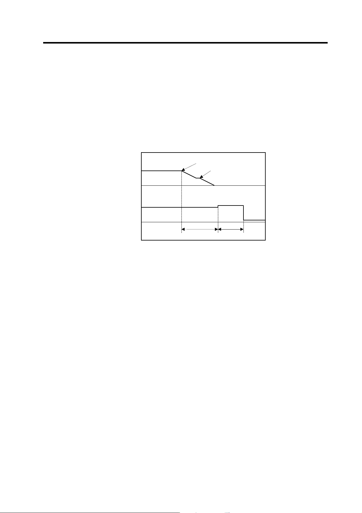
No. Abbr. Parameter name Details
Setting
range
Standard
SP255 DA1MPY DA output channel 1
magnification
0
SP256 DA2MPY DA output channel 2
magnification
Set the output magnification with a 1/256 unit.
When "0" is set, the magnification will be the same as "256".
-32768 to
32767
(1/256-fold)
0
5. Spindle Adjustment
5 - 5
(3) Control signal output (Data No. 80 to 87)
A hexadecimal display is converted into a decimal and output. The method of calculating the
magnification is the same as (2). The status cannot be output for each bit, so output the status for
all 16 bits.
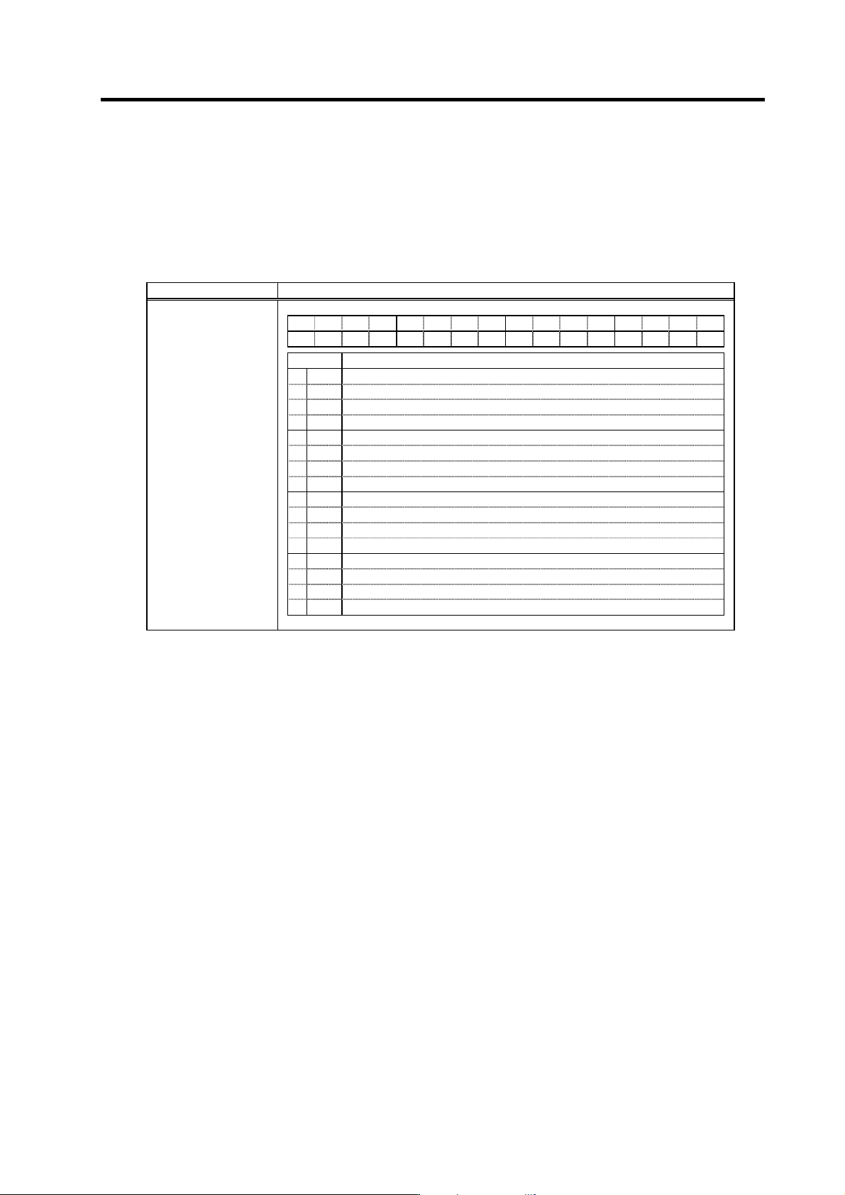
(Example) Orientation indexing control
With orientation indexing control, the following operations of the "Control output 4" can be
observed as shown on the right:
bit4: Orientation completed
bit7: Indexing positioning completed
Note that the weight of the D/A output differs for each bit.
Orientation indexing control sequence output
Orientation start
Orientation speed
Motor speed
Time
Control output 4
5[V]
Orientation time
Orientation
complete
0
10[V]
5
Indexing time
Indexing
complete
5. Spindle Adjustment
5 - 6
5-2 Spindle control signal
The sequence input/output signals exchanged between the NC and spindle drive unit are explained in
this section. The status of each signal is displayed on the NC SPINDLE MONITOR screen.
5-2-1 Spindle control input (NC to SP)
(1) Spindle control input 1
Name Details
F E D C B A 9 8 7 6 5 4 3 2 1 0
G1 MAC TL3 TL2 TL1
ALMR
PRM SRV RDY
bit Details
0
RDY
READY ON command
1
SRV
Servo ON command
2
3
4
5
6
PRM
Parameter conversion command
7
ALMR
Drive unit alarm reset command
8
TL1
Torque limit 1
9
TL2
Torque limit 2
A
TL3
Torque limit 3
B
MAC
Pole position detection check command (only for MDS-C1-SPM)
C
D
E
F
G1
Cutting
Spindle control input 1
bit0. READY ON command (RDY)
This signal is input when preparations to rotate the motor are completed. The forward run and
reverse run commands will not be accept ed even if input before this signal turns ON.
bit1. Servo ON command (SRV)
This is input for position control, excluding orientation. If this signal is not ON, position control will
not be executed even if the spindle control mode selection command's combination indicates the
position control mode.
bit6. Parameter conversion command (PRM)
This is started when the spindle parameters are converted on the NC screen.
bit7. Drive unit alarm reset command (ALMR)
This turns ON while NC reset is input. Spindle alarms that can be reset with NR are reset.