bnp-b2365(eng)b.pdf - 第254页
5. Spindle Adjustment 5 - 9 (3) Spindle control input 3 Name Details F E D C B A 9 8 7 6 5 4 3 2 1 0 PCHG MS LCS ORC WRI WRN SRI S RN GR2 G R1 SC5 SC4 SC3 SC2 SC1 bit Details 0 SC1 Spindle control mode selection command …
5. Spindle Adjustment
5 - 8
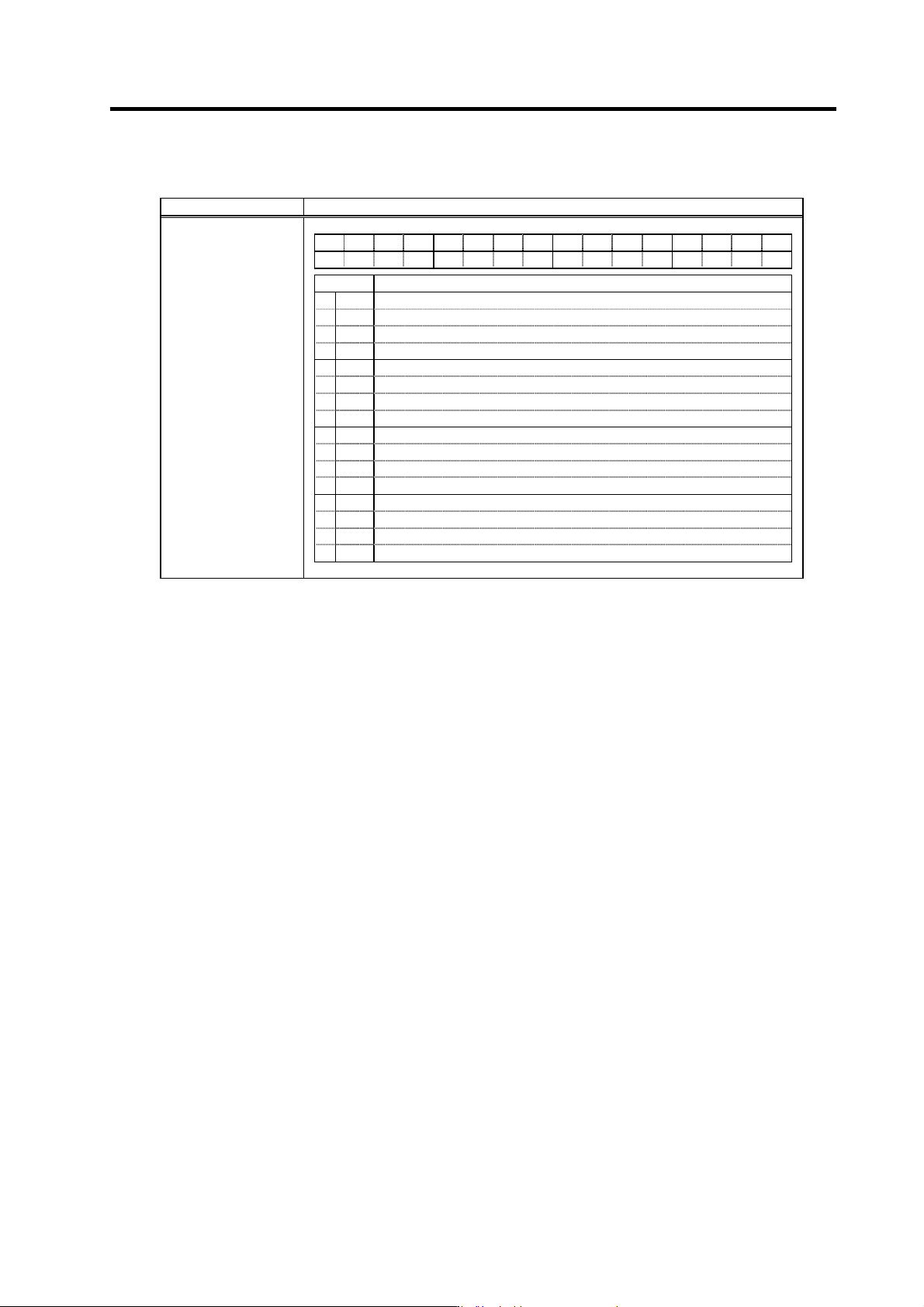
(2) Spindle control input 2
Name Details
F E D C B A 9 8 7 6 5 4 3 2 1 0
DAR PAR
bit Details
0
1
2
3
4
5
6
7
8
9
A
B
C
PAR
PS alarm history clear
D
E
DAR
Alarm history clear
F
Spindle control input 2
bitC. PS alarm history clear(PAR)
This signal turns ON when clearing alarm history for power supply.
bitE. Alarm history delete(DAR)
This signal turns ON when clearing alarm history for driver.
5. Spindle Adjustment
5 - 9
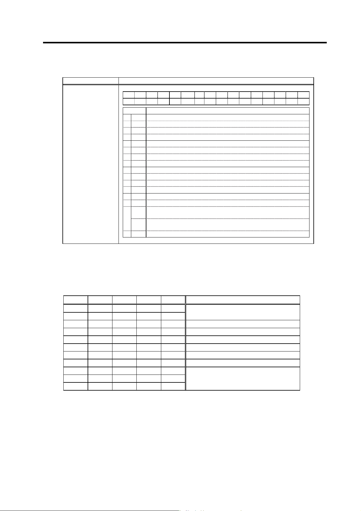
(3) Spindle control input 3
Name Details
F E D C B A 9 8 7 6 5 4 3 2 1 0
PCHG
MS LCS ORC WRI WRN SRI SRN GR2 GR1 SC5 SC4 SC3 SC2 SC1
bit Details
0
SC1
Spindle control mode selection command 1
1
SC2
Spindle control mode selection command 2
2
SC3
Spindle control mode selection command 3
3
SC4
Spindle control mode selection command 4
4
SC5
Spindle control mode selection command 5
5
GR1
Gear selection command 1
6
GR2
Gear selection command 2
7
8
SRN
Forward run start command
9
SRI
Reverse run start command
A
WRN
Indexing forward run command
B
WRI
Indexing reverse run command
C
ORC
Orientation start command
D
LCS
L coil selection command (When using coil changeover motor)
MS
<<For MDS-C1-SP>>
Sub-motor selection command (for 1-drive unit 2-motor changeover)
E
MCS
<<For MDS-C1-SPM>>
M coil selection command (when using coil changeover motor)
F
PCHG
Position changeover mode selection
Spindle control input 3
bit0. Spindle control mode selection command 1 (SC1)
bit1. Spindle control mode selection command 2 (SC2)
bit2. Spindle control mode selection command 3 (SC3)
bit3. Spindle control mode selection command 4 (SC4)
bit4. Spindle control mode selection command 5 (SC5)
SC5 SC4 SC3 SC2 SC1 Control mode
0 0 0 * *
0 0 1 * *
Speed control
0 1 0 * * Synchronous tap control
0 1 1 0 0 C-axis control, No. 1 gain selection
0 1 1 0 1 C-axis control, No. 2 gain selection
0 1 1 1 0 C-axis control, No. 3 gain selection
0 1 1 1 1 Setting prohibited
1 0 0 * * Spindle synchronous control
1 0 1 * *
1 1 0 * *
1 1 1 * *
Setting prohibited
(Note) The asterisk indicates 1 or 0.
5. Spindle Adjustment
5 - 10
bit5. Gear selection command 1 (GR1)
bit6. Gear selection command 2 (GR2)
This selects the number of spindle gear stages required to carry out orientation operation or
various position control operation.
GR2 GR1 Gear ratio
0 0 SP025, SP029
0 1 SP026, SP030
1 0 SP027, SP031
1 1 SP028, SP032
Related spindle parameters
No. Abbr. Parameter name Details
Setting
range
Standard
setting
SP025 GRA1* Spindle gear teeth
count 1
Set the number of gear teeth of the spindle corresponding to
gear 000.
1 to 32767 1
SP026 GRA2* Spindle gear teeth
count 2
Set the number of gear teeth of the spindle corresponding to
gear 001.
1 to 32767 1
SP027 GRA3* Spindle gear teeth
count 3
Set the number of gear teeth of the spindle corresponding to
gear 010.
1 to 32767 1
SP028 GRA4* Spindle gear teeth
count 4
Set the number of gear teeth of the spindle corresponding to
gear 011.
1 to 32767 1
SP029 GRB1* Motor shaft gear
teeth count 1
Set the number of gear teeth of the motor shaft corresponding
to gear 000.
1 to 32767 1
SP030 GRB2* Motor shaft gear
teeth count 2
Set the number of gear teeth of the motor shaft corresponding
to gear 001.
1 to 32767 1
SP031 GRB3* Motor shaft gear
teeth count 3
Set the number of gear teeth of the motor shaft corresponding
to gear 010.
1 to 32767 1
SP032 GRB4* Motor shaft gear
teeth count 4
Set the number of gear teeth of the motor shaft corresponding
to gear 011.
1 to 32767 1
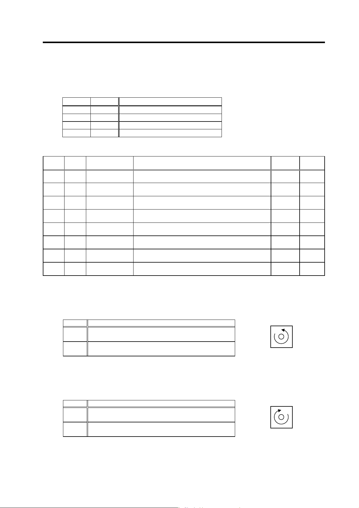
bit8. Forward run start command (SRN)
This is an operation command. The speed command must also be designated to rotate the motor.
If the orientation command is input, the orientation operation will have the priority.
SRN Explanation
1 (ON)
The motor rotates in the counterclockwise direction (CCW) looking
from the shaft at the commanded speed.
0 (OFF)
The motor decelerates to a stop.
After stopping, the drive unit's power module turns OFF.
bit9. Reverse run start command (SRI)
This is an operation command. The speed command must also be designated to rotate the motor.
If the orientation command is input, the orientation operation will have the priority.
SRN Explanation
1 (ON)
The motor rotates in the clockwise direction (CW) looking from the
shaft at the commanded speed.
0 (OFF)
The motor decelerates to a stop.
After stopping, the drive unit's power module turns OFF.
Spindle motor rotation direction
Counterclockwise
direction
Spindle motor rotation direction
Clockwise direction