bnp-b2365(eng)b.pdf - 第257页
5. Spindle Adjustment 5 - 12 <<For MDS-C1-SP >> bitE. Sub-motor selection command (MS) This command input si gnal is used to select su b-motor when changing over 1-drive unit 2- motor (spindle motor/general p…
5. Spindle Adjustment
5 - 11
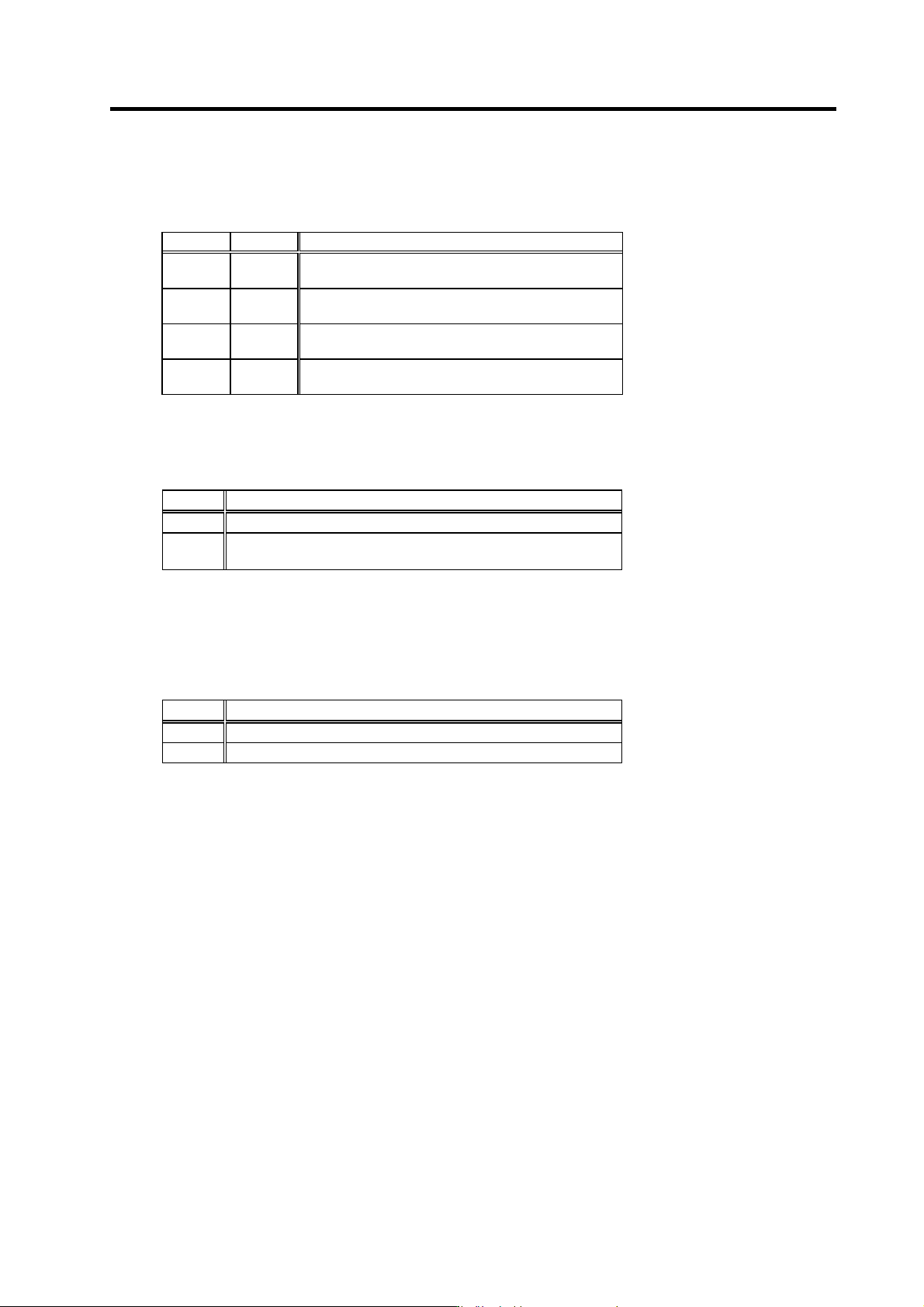
bitA. Indexing forward run command (WRN)
bitB. Indexing reverse run command (WRI)
This is valid when the orientation start command is ON.
WRI WRN Explanation
1
(ON)
1
(ON)
Setting prohibited.
0
(OFF)
1
(ON)
Indexing is carried out in the counterclockwise (CCW)
direction looking from the motor end.
1
(ON)
0
(OFF)
Indexing is carried out in the clockwise (CW) direction
looking from the motor end.
0
(OFF)
0
(OFF)
Indexing is not carried out.
bitC. Orientation start command (ORC)
This signal is used to start orientation. Orientation has a priority when the orientation start
command is input.
ORC Explanation
1 (ON) Orientation starts regardless of the run command (SRN, SRI).
0 (OFF)
When a run command (SRN, SRI) is selected, the rotation starts again
at the commanded speed.
bitD. L coil selection command (LCS)
This command is input to select the coil method for changing the coil. Note that coil changeover is
not possible when orientation is commanded. The coil is fixed when the orientation command is
input.
LCS Explanation
1 (ON) The low-speed command is selected.
0 (OFF) The high-speed command is selected.
5. Spindle Adjustment
5 - 12
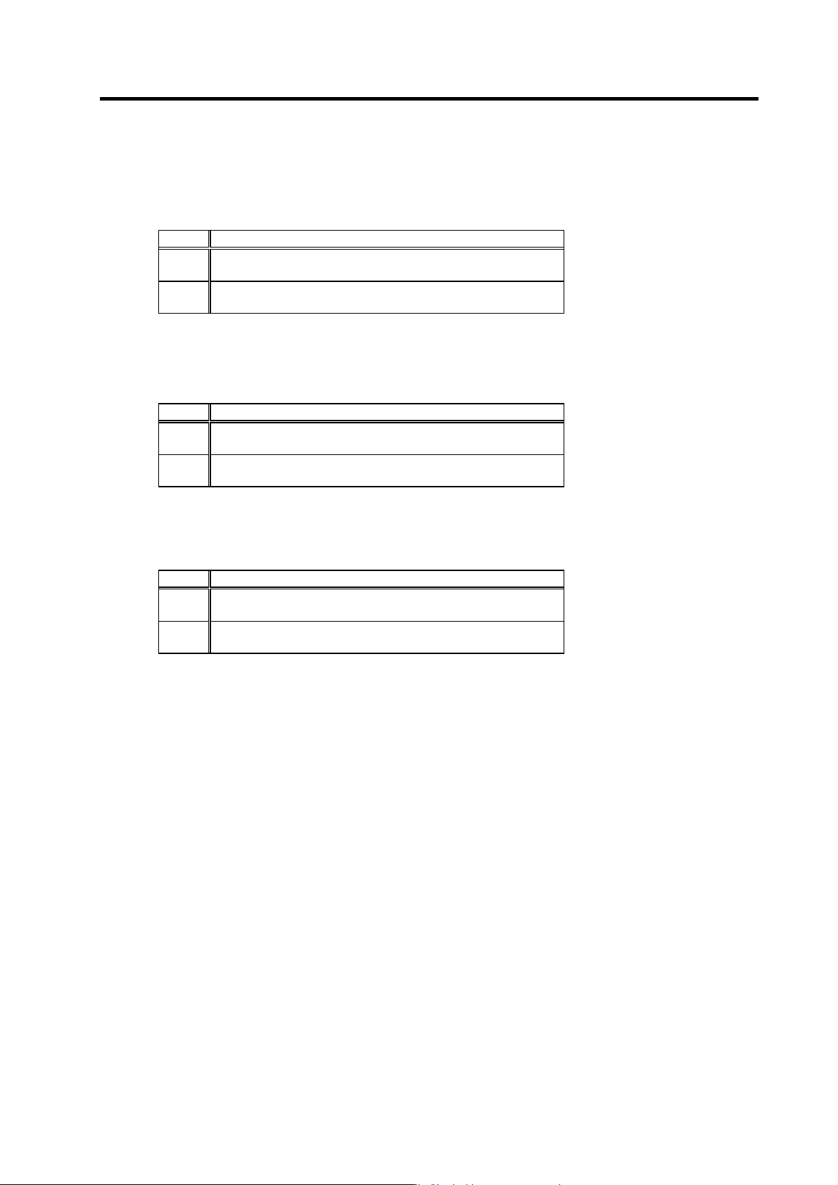
<<For MDS-C1-SP>>
bitE. Sub-motor selection command (MS)
This command input signal is used to select sub-motor when changing over 1-drive unit 2-motor
(spindle motor/general purpose motor).
MS Explanation
1
(ON)
Sub-motor is selected.
0
(OFF)
Main-motor is selected.
<<For MDS-C1-SPM>>
bitE. M coil selection command (MCS)
This command is input to select medium-speed coil when using the medium-sp eed coil.
MCS Explanation
1
(ON)
Medium-speed command is selected.
0
(OFF)
High-speed command is selected.
bitF. Position changeover mode selection (PCHG)
This command is input to select changeover operation from speed control to position control
(synchronous tap control, C-axis control and spindle synchronous control.)
PCHG Explanation
1
(ON)
No zero point return is selected.
0
(OFF)
With zero point return is selected.
5. Spindle Adjustment
5 - 13
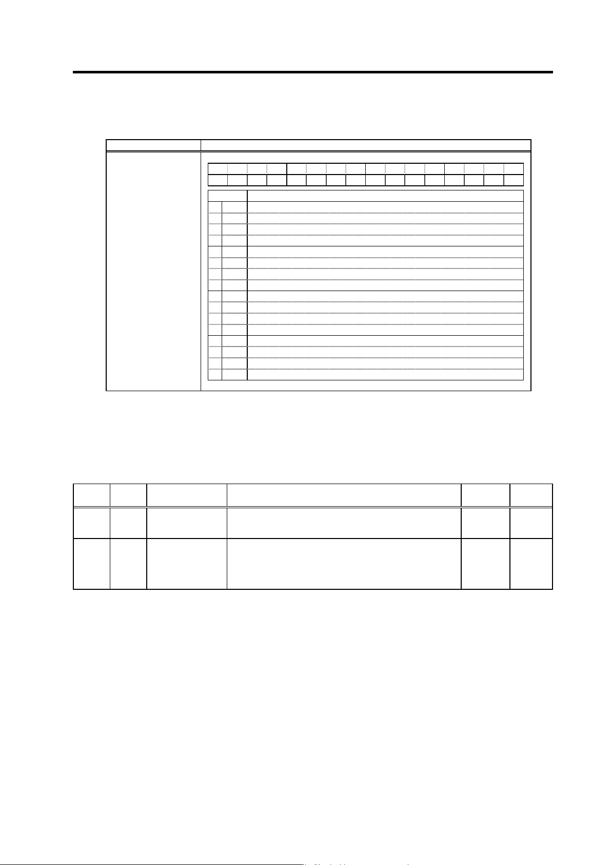
(4) Spindle control input 4
Name Details
F E D C B A 9 8 7 6 5 4 3 2 1 0
TLUP
OSPC
PYVC
bit Details
0
1
2
3
4
5
6
7
8
9
A
B
PYVC
Minimum excitation rate changeover request
C
OSPC
Orientation speed changeover request
D
E
F
TLUP
Spindle holding force up
Spindle control input 4
bitB. Minimum excitation rate changeover request (PYVC)
This command selects the minimum excita tion rate of weak excitation control.
When SP033/bit8=1, the minimum excitation rate changes over from SP056 to SP116 by turning
ON this signal.
Related spindle parameters
No. Abbr. Parameter name Details
Setting
range
Standard
SP056 PYVR Variable excitation
(min value)
Set the minimum value of the variable excitation rate.
Select a smaller value when gear noise is too high.
Lager value is more effective on impact response.
0 to 100
(%)
50
SP116 OPYVR Minimum excitation
value after
changeover (2nd
minimum excitation
rate)
Set the minimum excitation rate when position control input or
external input is selected.
0 to 100
(%)
0