bnp-b2365(eng)b.pdf - 第261页
5. Spindle Adjustment 5 - 16 bitB. Magnetic pole position checked (MAO) This signal turns ON when magnetic pole position is checked. bitD. Z-phase passed (ZFIN) This signal turns ON whe n the Z-phase is passed fo r the f…
5. Spindle Adjustment
5 - 15
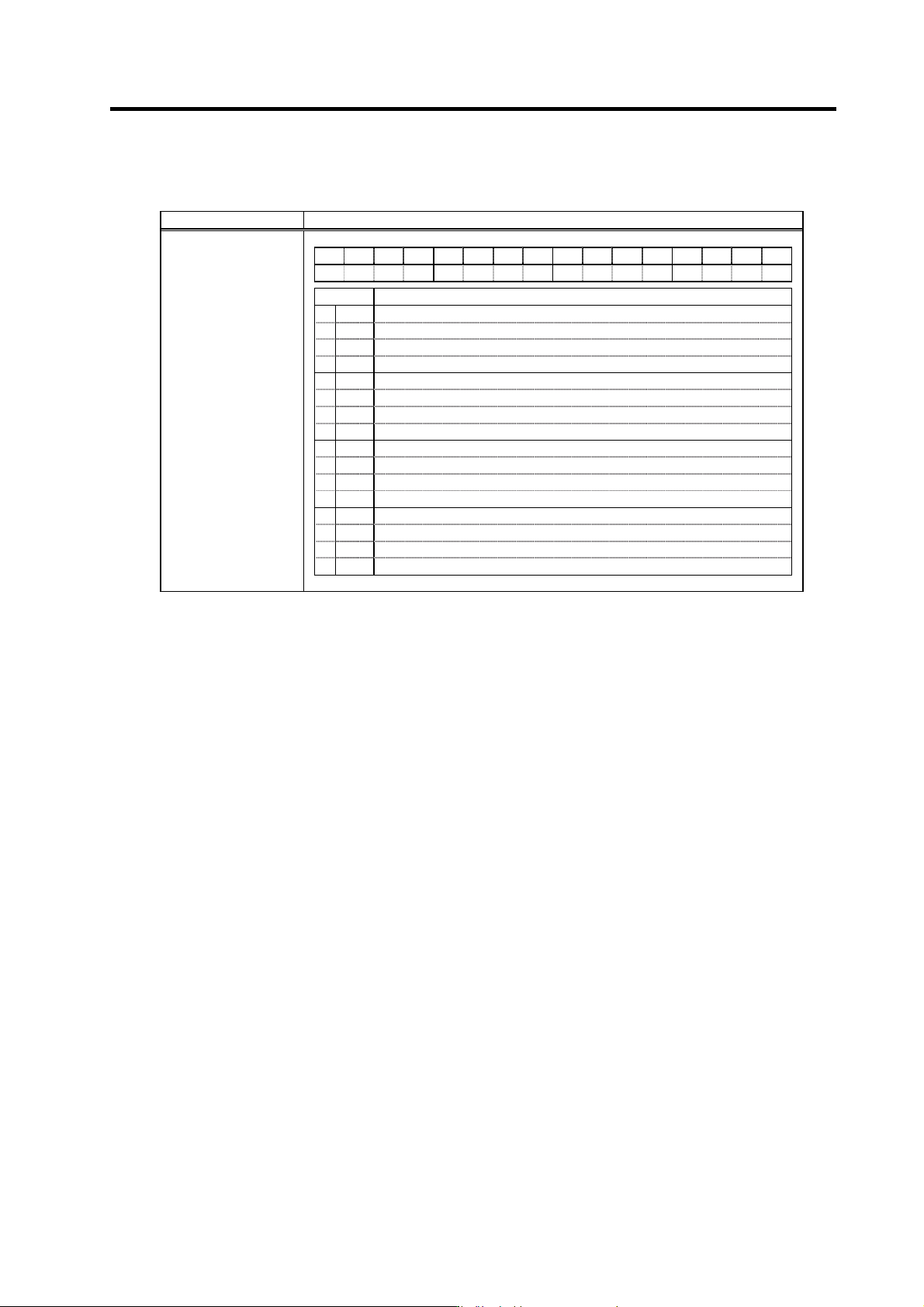
5-2-2 Spindle control output (SP to NC)
(1) Spindle control output 1
Name Details
F E D C B A 9 8 7 6 5 4 3 2 1 0
CL INP ZFIN MAO
TL3A TL2A TL1A
ALM
PRMA
WRN
SON RON
bit Details
0
RON
In READY ON
1
SON
In servo ON
2
3
4
WRN
In drive unit warning
5
6
PRMA
In parameter conversion
7
ALM
In drive unit alarm
8
TL1A
In torque limit 1 signal input
9
TL2A
In torque limit 2 signal input
A
TL3A
In torque limit 3 signal input
B
MAO
Magnetic pole position checked (Only for MDS-C1-SPM)
C
D
ZFIN
Z-phase passed
E
INP
In position loop in-position
F
CL
Limiting current
Spindle control output 1
bit0. In READY ON (RON)
When the READY ON signal is input from the NC, if there is no abnormality, this signal turns on in
approx. one second. If the start sign al (forward run, reverse run, orientation) is turne d ON while this
signal is ON, the motor will start rotating. If an alarm occurs in the spindle drive unit, this signal will
turn OFF. If the READY ON signal from the NC turns OFF while the spindle motor is rotating, the
motor will decelerate to a stop, but this signal will remain ON until the motor stops.
bit1. In servo ON (SON)
This signal turns ON after position control is switched when performing position control except for
the orientation.
bit4. In drive unit warning (WRN)
This signal turns ON when a warning is occurring in the spindle drive unit.
bit6. In parameter conversion (PRMA)
The parameters sent fro m the NC are converted into effective parameters for spindle control.
bit7. In drive unit alarm (ALM)
This signal turns ON when an alarm is occurring in the spindle drive unit.
bit8. In torque limit 1 signal input (TL1A)
bit9. In torque limit 2 signal input (TL2A)
bitA. In torque limit 3 signal input (TL3A)
The respective signal turns ON when the torque limit signal 1 to 3 is input.
5. Spindle Adjustment
5 - 16
bitB. Magnetic pole position checked (MAO)
This signal turns ON when magnetic pole position is checked.
bitD. Z-phase passed (ZFIN)
This signal turns ON when the Z-phase is passed for the first time after servo ON during position
control.
bitE. In position loop in-position (INP)
During position loop control, this signal turns ON if the position droop drops below the value set
with SP153 (CINP) during C-axis control, SP185 (SINP) during spindle synchronous control, and
SP217 (TINP) during synchronous tap control.
Related spindle parameters
No. Abbr. Parameter name Details
Setting
range
Standard
SP153 CINP C-axis control
in-position width
Set the position error range for outputting the in-position signal
during C-axis control.
(HEX setting)
0000 to
FFFF
(1/1000deg)
03E8
SP185 SINP Spindle synchronous
control
In-position width
Set the position error range for output of the in-position signal in
the spindle synchronous control mode.
1 to 2880
(1/16deg)
16
SP217 TINP Synchronized
tapping control
in-position width
Set the position error range for output of the in-position during
synchronized tapping control.
1 to 2880
(1/16deg)
16
bitF. Limiting current (CL)
This signal turns ON if a load higher than the spindle's excessive load withstand level is applied
during spindle motor rotation. This may also turn ON during motor acceleration/deceleration.
5. Spindle Adjustment
5 - 17
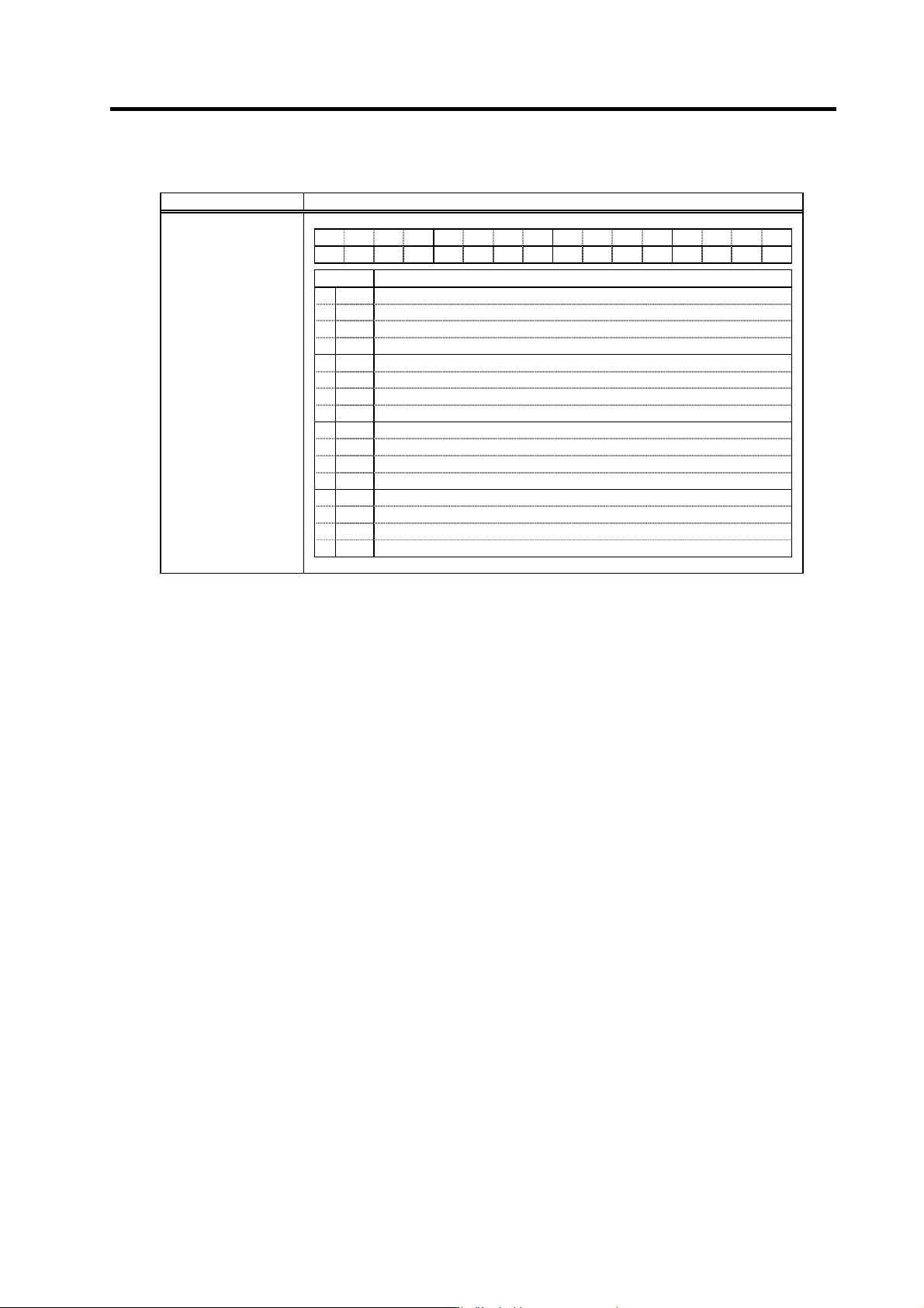
(2) Spindle control output 2
Name Details
F E D C B A 9 8 7 6 5 4 3 2 1 0
DARA
PARA
bit Details
0
1
2
3
4
5
6
7
8
9
A
B
C
PARA
In PS alarm history clear
D
E
DARA
In alarm history in clear
F
Spindle control output 2
bitC. In PS alarm history clear (PARA)
This signal turns ON while clearing power supply alarm history.
bitE. In alarm history clear (DARA)
This signal turns ON while clearing drive alarm history.