bnp-b2365(eng)b.pdf - 第262页
5. Spindle Adjustment 5 - 17 (2) Spindle control output 2 Name Details F E D C B A 9 8 7 6 5 4 3 2 1 0 DARA PARA bit Details 0 1 2 3 4 5 6 7 8 9 A B C PARA In PS alarm history clear D E DARA In alarm history in clear F S…
5. Spindle Adjustment
5 - 16
bitB. Magnetic pole position checked (MAO)
This signal turns ON when magnetic pole position is checked.
bitD. Z-phase passed (ZFIN)
This signal turns ON when the Z-phase is passed for the first time after servo ON during position
control.
bitE. In position loop in-position (INP)
During position loop control, this signal turns ON if the position droop drops below the value set
with SP153 (CINP) during C-axis control, SP185 (SINP) during spindle synchronous control, and
SP217 (TINP) during synchronous tap control.
Related spindle parameters
No. Abbr. Parameter name Details
Setting
range
Standard
SP153 CINP C-axis control
in-position width
Set the position error range for outputting the in-position signal
during C-axis control.
(HEX setting)
0000 to
FFFF
(1/1000deg)
03E8
SP185 SINP Spindle synchronous
control
In-position width
Set the position error range for output of the in-position signal in
the spindle synchronous control mode.
1 to 2880
(1/16deg)
16
SP217 TINP Synchronized
tapping control
in-position width
Set the position error range for output of the in-position during
synchronized tapping control.
1 to 2880
(1/16deg)
16
bitF. Limiting current (CL)
This signal turns ON if a load higher than the spindle's excessive load withstand level is applied
during spindle motor rotation. This may also turn ON during motor acceleration/deceleration.
5. Spindle Adjustment
5 - 17
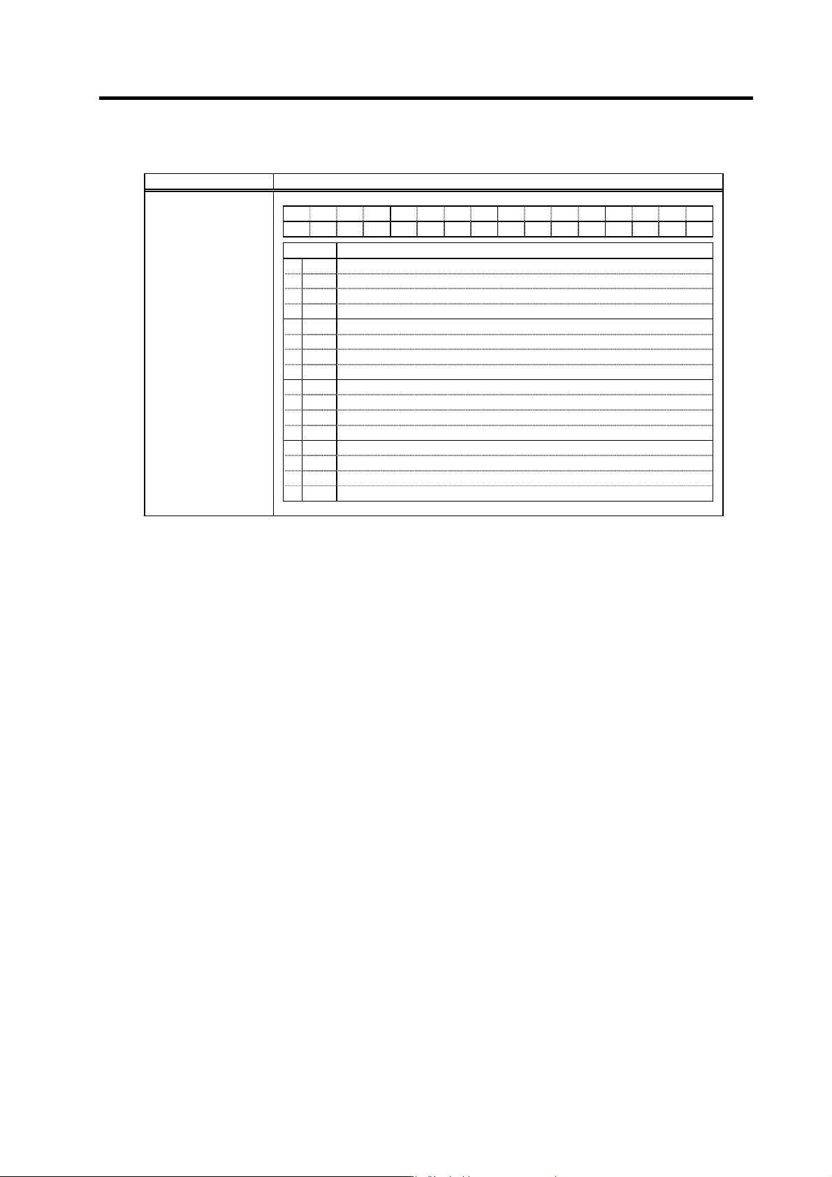
(2) Spindle control output 2
Name Details
F E D C B A 9 8 7 6 5 4 3 2 1 0
DARA
PARA
bit Details
0
1
2
3
4
5
6
7
8
9
A
B
C
PARA
In PS alarm history clear
D
E
DARA
In alarm history in clear
F
Spindle control output 2
bitC. In PS alarm history clear (PARA)
This signal turns ON while clearing power supply alarm history.
bitE. In alarm history clear (DARA)
This signal turns ON while clearing drive alarm history.
5. Spindle Adjustment
5 - 18
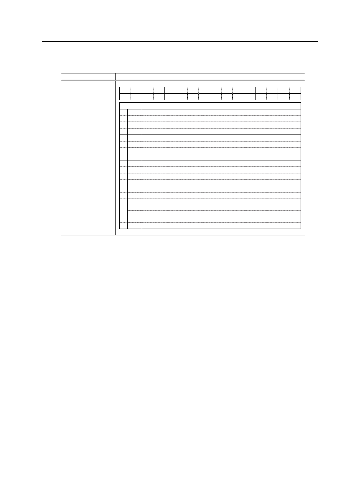
(3) Spindle control output 3
Name Details
F E D C B A 9 8 7 6 5 4 3 2 1 0
LCSA
ORCA
WRIA
WRNA
SRIA
SRNA
GR2A GR1A SC5A SC4A SC3A SC2A SC1A
bit Details
0
SC1A
Inputting spindle control mode selection command 1 signal
1
SC2A
Inputting spindle control mode selection command 2 signal
2
SC3A
Inputting spindle control mode selection command 3 signal
3
SC4A
Inputting spindle control mode selection command 4 signal
4
SC5A
Inputting spindle control mode selection command 5 signal
5
GR1A
Inputting gear selection command 1 signal
6
GR2A
Inputting gear selection command 2 signal
7
8
SRNA
Motor in forward run
9
SRIA
Motor in reverse run
A
WRNA
In forward run indexing
B
WRIA
In reverse run indexing
C
ORCA
In orientation start command signal
D
LCSA
L coil selected (when using the coil changeover motor)
MSA
<<For MDS-C1-SP>>
In sub-motor selection (for 1-drive unit 2-motor changeover)
E
MCSA
<<For MDS-C1-SPM>>
In M coil selection (when using coil changeover motor)
F
Spindle control output 3
bit0. Inputting spindle control mode selection command 1 signal (SC1A)
bit1. Inputting spindle control mode selection command 2 signal (SC2A)
bit2. Inputting spindle control mode selection command 3 signal (SC3A)
bit3. Inputting spindle control mode selection command 4 signal (SC4A)
bit4. Inputting spindle control mode selection command 5 signal (SC5A)
The respective signal turns ON when the spindle control mode selection command 1 to 5 is input.
bit5. Inputting gear selection command 1 signal (GR1A)
bit6. Inputting gear selection command 2 signal (GR2A)
The respective sign al turns ON when the gear selection command 1 or 2 is input.
bit8. Motor in forward run (SRNA)
This signal turns ON while the start signal is input and the motor is rotating in the CCW direction
looking from the motor shaft. This signal may turn ON and OFF if the motor speed is several r/min
or less.
bit9. Motor in reverse run (SRIA)
This signal turns ON while the start signal is input and the motor is rotating in the CW direction
looking from the motor shaft. This signal may turn ON and OFF if the motor speed is several r/min
or less.