bnp-b2365(eng)b.pdf - 第270页
5. Spindle Adjustment 5 - 25 bitC. Orientation speed changeov er state (OSP A) This signal turns ON in response to orie ntation speed (control input 4/bitB). bitD. In automatic adjustment (ATA) This signal turns ON while…
5. Spindle Adjustment
5 - 24
bit7. Index positioning completed (WRCF)
This signal turns ON during indexing operation when the spindle position reaches the in-position
range in respect to the target stop position. Once this signal turns ON it will remain ON regardless
of the spindle position until the orientation signal turns OFF or the next indexing operation signal is
input.
This signal will turn OFF for the time set with paramet er SP103 (FTM) when the i ndexing operation
signal is input even if the current stop point and the next indexing position are in the in-position
range.
Related spindle parameter
No. Abbr. Parameter name Details
Setting
range
Standard
SP103 FTM* Index positioning
completion OFF time
timer
Set the time for forcedly turn OFF the index positioning
completion signal (different from the orientation completion
signal) after the leading edge of the indexing start signal.
0 to 10000
(ms)
200
bit8. In 1-drive unit 2-motor changeo ver (MTC)
This signal turns ON during motor changeover with 1-drive unit 2-motor specification.
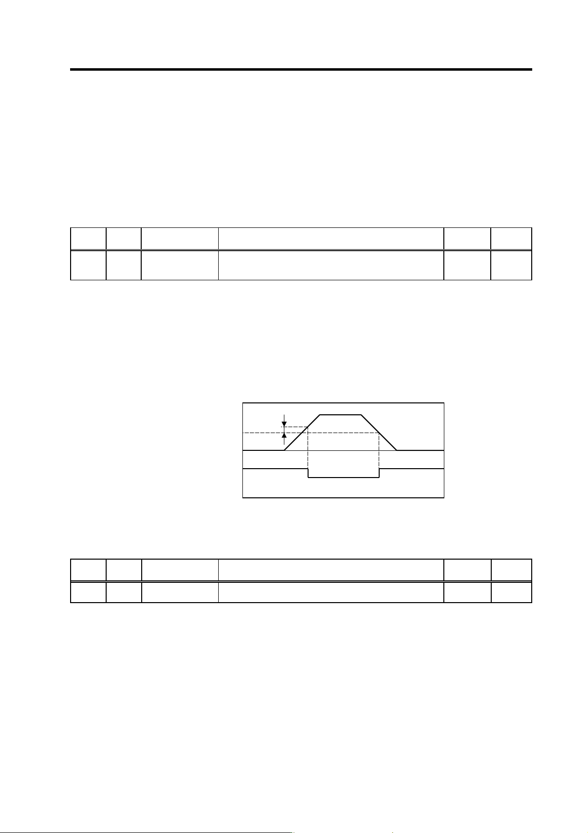
bit9. Speed detection 2 (SD2)
This signal turns ON when the motor speed drops below the value set with parameter SP058
(SDT2). The ON to OFF hysteresis width is fixed at 15r/min. This signal turns ON when the motor
speed drops below the set speed regardless of the input signal state.
Speed detection 2 (SD2) sequence
Related spindle parameter
No. Abbr. Parameter name Details
Setting
range
Standard
SP058 SDT2* Speed detection
setting value 2
Set the motor speed for carry out speed detection 2 output. 0 to 32767
(r/min)
0
bitB. In minimum weak excitation value changeov er (PYDA)
This signal turns ON in response to minimum excitation changeover request (control input 4/bitB).
15r/min
Motor speed
Speed detection 2 (SD2)
ON
OFF
SP058
0
5. Spindle Adjustment
5 - 25
bitC. Orientation speed changeov er state (OSPA)
This signal turns ON in response to orientation speed (control input 4/bitB).
bitD. In automatic adjustment (ATA)
This signal turns ON while the spindle is starting during Z-phase automatic adjustment of the PLG
with MDS-C1-SPM.
bitE. Spindle holding force increased (TLUA)
This signal turns ON while the spindle holding force up (TLUP) si gnal is input.
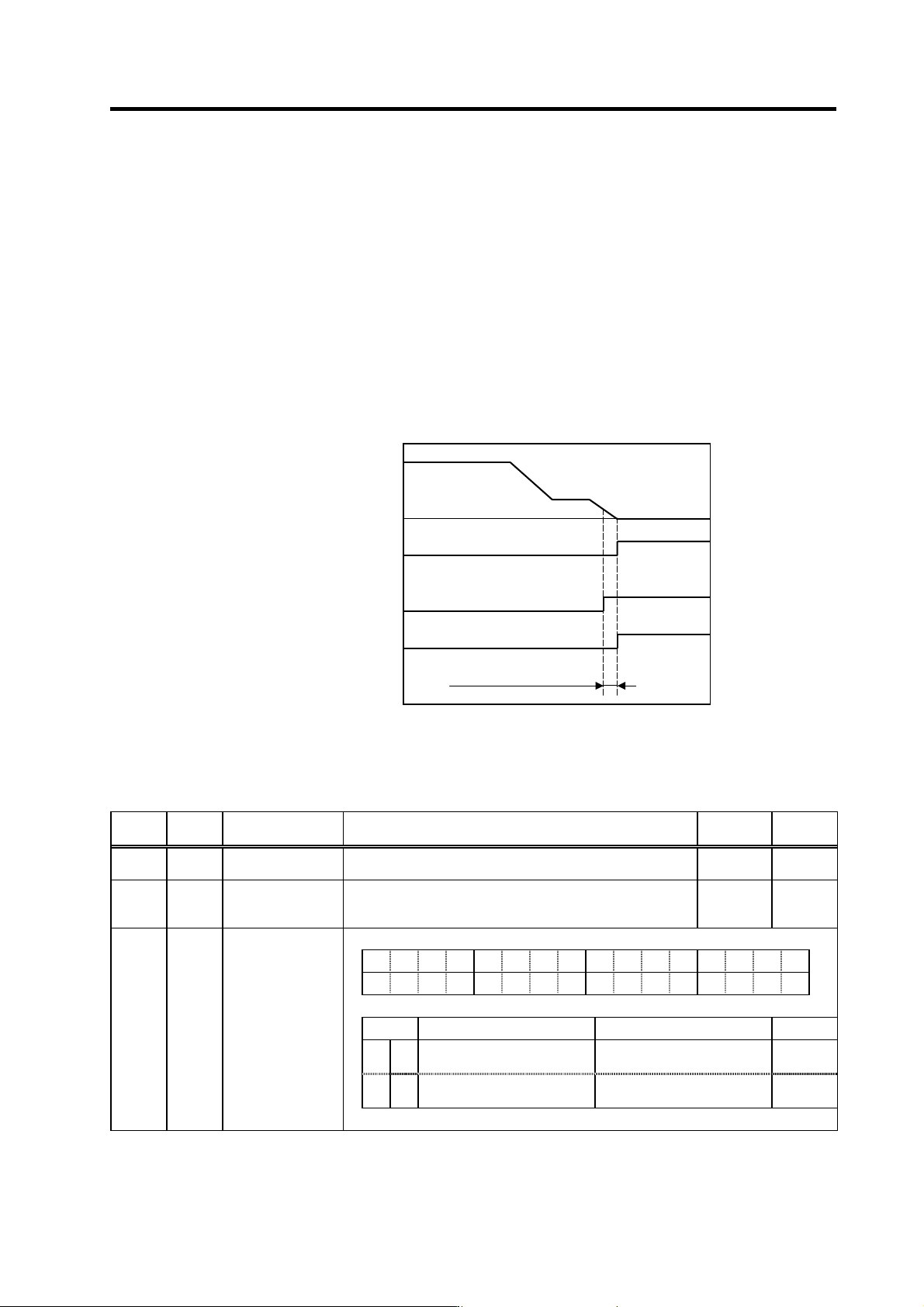
bitF. 2nd orientation complete (ORF2)
When orientation complete advance is valid, this signal turns ON as in-position width determined
by required SP004 is reach ed.
Related spindle parameters
No. Abbr. Parameter name Details
Setting
range
Standard
SP004 OINP Orientation
in-position width
Set the position error range in which an orientation completion
signal is output.
1 to 2880
(1/16deg)
16
SP101 DINP* Orientation advance
in-position width
When using the orientation completed advance function, set the
in-position width that is larger than the normal in-position width
defined in SP004 (OINP).
1 to 2880
(1/16deg)
16
F EDCBA98765 4 3 2 10
ostp orze ksft gchg ips2 zdir vg8x mdir fdir oscl pyfx dmin odi2 odi1
bit Meaning when set to 0 Meaning when set to 1
Standard
2 dmin
Orientation completion
advance invalid
Orientation c o m p l e t i o n a d v a n c e
valid
0
A ips2
2nd orientation completion
invalid
2nd orientation completion valid
0
SP097 SPECO* Orientation
specification
Orientation control
speed waveform
Sequence of 2nd orientation completed (ORF2)
Orientation complete (ORCF)
(during normal control)
ON
OFF
Orientation complete (ORCF)
(when advance control is valid)
ON
OFF
2nd orientation completed
(ORF2)
ON
OFF
Orientation complete advance
(SP101 setting)
0

5. Spindle Adjustment
5 - 26
5-3 Adjustment procedures for each control
5-3-1 Basic adjustments
(1) Items to check during trial operation
[1] Directly couple the motor and machine, and check the control status during m achine run-in.
[2] Check that the command speed and actual speed match.
If the speeds do not match, check spindle parameters again.
(Especially check SP017, SP034, SP040 and SP257 to SP384.)
[3] Check the NC parameters Slimit1 to 4, Smax 1 to 4, and Smini.
[4] Is the rotation smooth?
[5] Is there any abnormal noise?
[6] Are there any abnormal odors?
[7] Has the bearing temperatu re risen abnormally?
(2) Adjusting the spindle rotation speed
The rotation speed is received as digital signals from the NC, and thus does not need to be
adjusted. If the spindle rotation speed does not match the commanded value due to a dimensional
error, such as the pulley diameter, adjust the parameters with the following method.
[1] Set the spindle specification parameter slimit.
Slimit = SP017 × (deceleration rate between motor and spindle)
[2] Set the S command to half of the maximum spindle rotation speed, and then measure the
spindle rotation speed.
If the speeds do not match, change the Slimit value in small increments until the speed
matches.
[3] Set the S command to the maximum spindle rotation speed, and check whether the spindle
rotation speed matches.
[4] In machines involving gear changeover, etc., change the gears, and then adjust with steps [1]
to [3] above.