bnp-b2365(eng)b.pdf - 第275页
5. Spindle Adjustment 5 - 30 (3) Adjustment when the load inertia is large When the load inertia is large and acce leration time is 10s or more, excessive spe ed deviation alarm (ALM23) may occur because the time in whic…
5. Spindle Adjustment
5 - 29
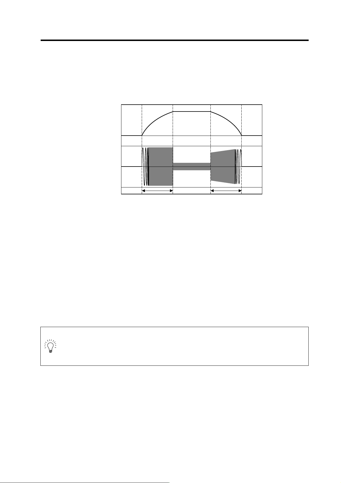
(2) Measuring the acceleration/deceleration waveforms
Measure the acceleration/deceleration waveforms by using the spindle drive unit's D/A output
function and check if theoretical acceleration/de celeration time is within ±15%. Refer to "5-1 D/A
output specifications for spindle drive unit" for details on D/A output functions.
Phase current FB output can be measured by the waveform for either U or V phase FB.
When acceleration/deceleration time does not match the theoretical value (an error rate 15% or
more), check the following items.
[1] There may be an error in calculating load inertia for the motor axis conversion used when
calculating the theoretical acceleration/deceleration time. Check the load inertia again.
[2] When acceleration time is long and deceleration time is short, friction torque is thought to be
large. Check load meter value at the maximum speed (spindle monitor screen). If the load is
10% or more, friction torque is thought to be relatively large. Mechanical friction, such as
bearing friction or timing belt friction, is assumed to be large. Measure the acceleration/
deceleration time again following trial run.
[3] Even if the problems above are not found, when acceleration/decel eration time does not match,
there may be a possibility of using spindle motor and spindle drive unit that are not specified, or
using wrong parameters. Check the spindle motor type and spindle drive unit type again, as
well as the spindle parameter settings.
POINT
1. There are cases where acceleration/d ecele ration waveforms cha nge dependin g
on the spindle temperature. Check the waveforms when the spindle temperature
is high (after continuous operation) and when it is low.
2. Conduct "3-5 Initial adjustment of spindle PLG" beforehand.
Speedometer output [V]
Acceleration/deceleratio n waveforms of spindle motor
0
4.0
2.5
1.0
U(V) phase current FB output [V]
Acceleration time: ta Deceleration time: td
5. Spindle Adjustment
5 - 30
(3) Adjustment when the load inertia is large
When the load inertia is large and acceleration time is 10s or more, excessive speed deviation
alarm (ALM23) may occur because the time in which deviation between speed command and
speed FB, which is the actual spindle motor rotation speed, exists is prolonged. In this case,
increase speed cushion 1 (SP019). When the acceleration time is 10s or less, use the standard
value 30 (300ms).
Alarm can be avoided by adjusting excessive speed deviation timer (SP055). However, i n this case,
alarm detection will be delayed during constant speed operation.
In order to improve current ripple waveforms during acceleration/deceleration, adjust by using
speed command dual cushion explained later.
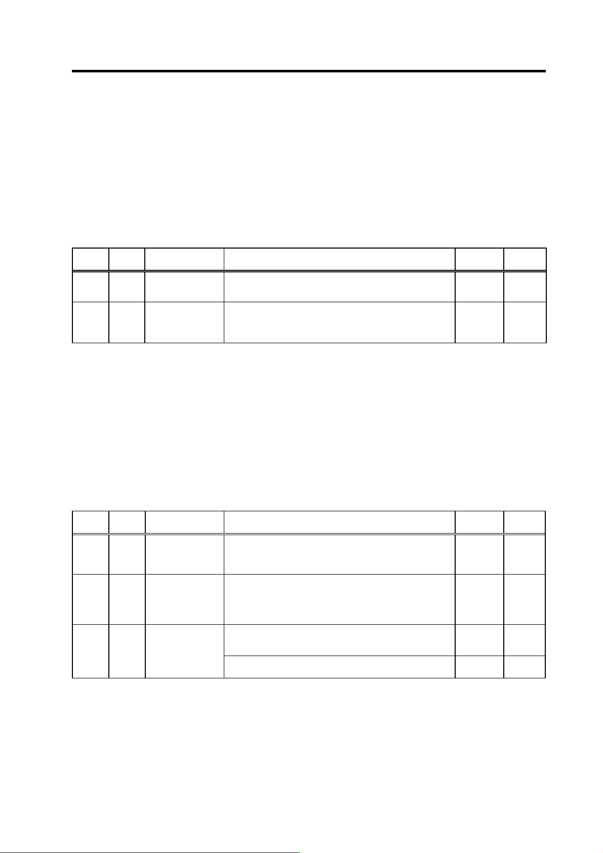
No. Abbr. Parameter name Details
Setting
range
Standard
SP019 CSN1* Speed cushion 1 Set the time constant for a speed command from "0" to the
maximum speed.
(This parameter is invalid during position loop control.)
1 to 32767
(10ms)
30
SP055 SETM* Excessive speed
deviation timer
Set the timer value until the excessive speed deviation alarm is
output.
The value of this parameter should be longer than the
acceleration/deceleration time.
0 to 60
(s)
12
(4) Adjustment when machine system vibration (nois e) is generated
When machine components such as gears produce vibration and noise, a machine resonance
suppressing filter (notch filter) can be set to eliminate the vibration. At the SP070 parameter,
specify the frequency of the vibration to be eliminated. This filter is enabled during all positioning
control modes, including speed control, orientation control, and synchronous tap control. If
vibration is generated or increased by setting this filter at low speeds, set a machine resonance
suppressing filter activation speed (SP076) to prevent the vibration.
When noise from the spindle motor seems excessive, a low-pass filter (SP213) can be set to
reduce the noise level. The low-pass filter frequency should be set as high as possible, as a low
frequency setting can impair spindle control.
No. Abbr. Parameter name Details
Setting
range
Standard
SP070 FHz Machine resonance
suppression filter
frequency
When machine vibration occurs in speed and position control,
set the frequency of the required vibration suppression.
Note that a value of 100Hz or more is set.
Set to "0" when not used.
0 to 3000
(Hz)
0
SP076 FONS Machine resonance
suppression filter
operation speed
When the vibration increases in motor stop (ex. in orientation
stop) when the machine vibration suppression filter is operated
by SP070, operate the machine vibration suppression filter at a
speed of this parameter or more.
When set to "0", this is validated for all speeds.
0 to 32767
(r/min)
0
<For MDS-C1-SP/SPH/SPM>
Set to reduce the noise generated from the spindle motor
Set the band of the low path filter
0 to 2250
(rad/s)
0 SP213 LPF Low path filter
<For MDS-C1-SPX/SPHX>
Not used. Set to "0".
0 0
5. Spindle Adjustment
5 - 31
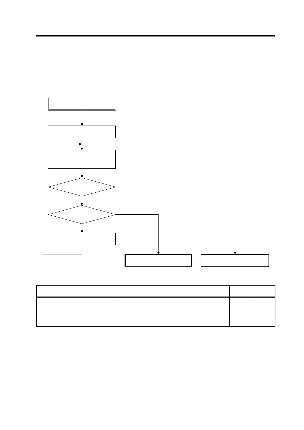
(5) Adjusting speed command dual-cushion
When a deceleration start causes rippling in the phase current FB waveform, or when a spindle
override change causes gear impact noise, the speed command dual-cushion (SP046) setting
should be adjusted. The smaller the SP046 setting value, the longer the acceleration/deceleration
time. Therefore, set SP046 value as high as possible, while observing the phase current FB
waveform, or while listening to the impact noise. (Setting upper limit = 5)
No. Abbr. Parameter name Details
Setting
range
Standard
SP046 CSN2* Speed command
dual cushion
For an acceleration/deceleration time constant defined in
SP019 (CSN1) , this parameter is used to provide smooth
movement only at the start of acceleration/deceleration.
As the value of this parameter is smaller, it moves smoother but
the acceleration/deceleration time becomes longer.
To make this parameter invalid, set "0".
0 to 1000 0
Adjusting SP046
Does waveform ripple or
impact noise occur?
Check for other causes
NO
Measure acceleration/deceleration
waveform at high speed
Change the spindle override
Increase SP046 by –1.
YES
Set SP046=5
YES
NO
SP046 adjustment completed
SP046=1 ?